 |
|
Part II - Bulletin Listings
WJ Series: 1999-2004 Model Years
Date: 05/28/99
Model year(s): 1999
Description: Noisy front propeller shaft rear constant velocity joint.
Details: Applies to models built prior to March 14, 1999. While driving, a noise may be noticed coming from the front propeller shaft. The noise may sound like popping, snapping and/or grinding. A driveline vibration may also be noticed. Closer inspection of the front propeller shaft may reveal a loss of lubricant from the rear constant velocity (CV) joint. The loss of lubricant may be due to a torn CV joint boot.
The condition may be the result of an interface fit between the back of the rear CV joint and the end of the transfer case front output shaft. This interface fit may cause the vent hole on the back of the rear CV joint to become blocked (sealed over). If the vent on the joint becomes blocked, it may cause pressure to build within the joint which may result in damage to boot of the rear CV joint.
Parts required: Date: 09/24/99
Model year(s): 1999-2000
Description: Diagnosis of the vehicle axle
Details: A sound may appear to be coming from the general area of the vehicle axle(s). The sound may be described as a growl, howl, or a whine. They may occur at different vehicle or engine speeds. They may also occur during different axle loading conditions i.e light driving, heavy driving, float, cruise or coast.
A correct and thorough diagnosis of the axle condition is perhaps the most important tool that the technician has in effecting a successful axle service. Because the transmission of an axle-like sound may be due to vehicle components other than the axle, a good diagnostic procedure is necessary in determining if the condition can be corrected by service to the internal axle components. Proper diagnosis may lead the technician to vehicle components other than the axle.
Date: 06/23/00 (supersedes 030799 dated 10/29/99)
Model year(s): 1999-2000
Description: A condition may exist where the vehicles owner may feel an intermittent bump (stop-bump) once the vehicle is brought to a full stop. The repair technician may erroneously diagnose this condition as a delayed transmission down shift into first gear. This condition may occur 3 to 20 seconds following the stop or when the load on the rear driveline is reduced (e.g., when the applied brake pressure is decreased). The stop-bump condition may be the result of a binding between the splined surfaces of
the rear propeller shaft slip yoke and the rear output shaft of either the transfer case or the transmission. As load on the driveline is reduced, the bound slip yoke will release
suddenly causing a bump-like sensation. The condition may be intermittent. If the above
condition has been experienced, then perform the Repair Procedure. The splined surfaces on the slip yoke section of the new propeller shaft are nickel coated to reduce the opportunity of binding.
Details: THIS BULLETIN APPLIES TO VEHICLES BUILT BEFORE SEPTEMBER 20,1999. A WJ EQUIPPED WITH A 4.0L ENGINE, A NV242 TRANSFER CASE, AND A 198 RBI (M35) REAR AXLE USES A DIFFERENT STYLE REAR PROPELLER SHAFT THAN THOSE WHICH ARE ADDRESSED IN THIS TECHNICAL SERVICE BULLETIN. FOR THIS VEHICLE, THE SPLINED SURFACES ON THE PROPELLER SHAFT SLIP YOKE AND THE TRANSFER CASE OUTPUT SHAFT ARE GREASED TO PREVENT A BINDING CONDITION AND DO NOT REQUIRE REPLACEMENT.
Parts required: Date: 11/26/99
Model year(s): 1999-2000
Description: Information on new WJ 186FBI front axle pinion gear flanged nut and ground collapsible spacer. These improvements entered vehicle production approximately October 30, 1999.
Details: Quality improvements have been made to two components in the WJ 186FBI (Dana model 30) front axle. These revised axle components include:
NOTE: WHEN MAKING REPAIRS TO THE FRONT AXLE, THE FLANGED PINION GEAR NUT IS TO BE ASSEMBLED TO THE PINION GEAR AND YOKE WITHOUT A WASHER. THE FLANGED PINION NUT REPLACES BOTH THE OLD STYLE PINION NUT AND THE PINION GEAR WASHER. THE OLD PINION GEAR WASHER IS LOCATED BEHIND AND NEXT TO THE OLD STYLE PINION NUT.
As a suggestion to assist the technician during tightening of the flanged pinion nut, a very small amount of a nickel anti-seize compound (p/n 05012249AA) may be placed only between the flanged surface of the pinion nut and its area of contact with the pinion yoke.
NOTE: NEVER ALLOW ANY LUBRICANT OR ANTI-SEIZE COMPOUND TO COME IN CONTACT WITH THE THREADS OF THE PINION GEAR OR THE PINION NUT. IF THIS WERE TO OCCUR, IT MAY CAUSE AN INACCURATE TORQUE READING.
Other than the inclusion of the revised pinion flanged nut and collapsible spacer, no changes to the current Service Manual axle repair procedure or torque specification is required.
Parts required: Date: 03/03/00
Model year(s): 1999-2000
Description: Concerns with a whine-like sound heard coming from the rear axle of the vehicle at speeds greater than 40 MPH. The sound may be more noticeable once the vehicle
powertrain components have reached normal operating temperatures.
Details: THIS BULLETIN APPLIES TO VEHICLES EQUIPPED WITH A 4.7L ENGINE BUILT BEFORE NOVEMBER 16, 1999. THIS REPAIR, BY ITSELF, WILL NOT CORRECT SIGNIFICANT REAR AXLE GENERATED SOUND. IN THOSE INCIDENCES, THIS REPAIR MAY BE MOST BENEFICIAL WHEN PERFORMED WITH AN AXLE REBUILD REPAIR.
Parts required: Date: 06/23/00 (supersedes 030799 dated 10/29/99)
Model year(s): 1999-2000
Description: A condition may exist where the vehicles owner may feel an intermittent bump (stop-bump) once the vehicle is brought to a full stop. The repair technician may erroneously diagnose this condition as a delayed transmission down shift into first gear. This condition may occur 3 to 20 seconds following the stop or when the load on the rear driveline is reduced (e.g., when the applied brake pressure is decreased). The stop-bump condition may be the result of a binding between the splined surfaces of
the rear propeller shaft slip yoke and the rear output shaft of either the transfer case or the transmission. As load on the driveline is reduced, the bound slip yoke will release
suddenly causing a bump-like sensation. The condition may be intermittent. If the above
condition has been experienced, then perform the Repair Procedure. The splined surfaces on the slip yoke section of the new propeller shaft are nickel coated to reduce the opportunity of binding.
Details: THIS BULLETIN APPLIES TO VEHICLES BUILT BEFORE SEPTEMBER 20,1999. A WJ EQUIPPED WITH A 4.0L ENGINE, A NV242 TRANSFER CASE, AND A 198 RBI (M35) REAR AXLE USES A DIFFERENT STYLE REAR PROPELLER SHAFT THAN THOSE WHICH ARE ADDRESSED IN THIS TECHNICAL SERVICE BULLETIN. FOR THIS VEHICLE, THE SPLINED SURFACES ON THE PROPELLER SHAFT SLIP YOKE AND THE TRANSFER CASE OUTPUT SHAFT ARE GREASED TO PREVENT A BINDING CONDITION AND DO NOT REQUIRE REPLACEMENT.
Parts required: Date: 07/21/00
Model year(s): 1999-2000 (vehicles with V8 only)
Description: This bulletin involves the replacement of the front propshaft, axle yoke, and transfer case yoke. This bulletin also involves selectively erasing and reprogramming the Transmission Control Module or TCM (with calibration 99Ver9.0 or 00Ver9.0), and if necessary, reprogramming the Powertrain Control Module or PCM (with calibration 99Cal19A or 00Cal16A).
Details: The customer may experience powertrain related sound(s) which may be described as front axle whine or as 2,200 to 2,400 engine rpm moan. One or both sounds may be noticed at the same time or separately during different modes of driving.
The front axle whine-like sound may occur during any vehicle speed and during acceleration, coast, or float driving modes. The moan-like sound will normally occur when the transmission is in top gear (overdrive) and the engine is running between speeds of 2,200 to 2,400 rpm. The moan-like sound will normally fade in and out (beat) while the throttle is held in a steady state or when the throttle is being depressed to accelerate the vehicle. The beat may increase in frequency as the engine speed increases. The moan-like sound will not occur if the transmission is shifted to a lower gear (overdrive button depressed) or if the throttle is released. A revised front propeller shaft addresses the whine-like sound from the front axle area. The revision to the TCM software adds a final gear ratio to the transmission. This new final gear ratio will cause a substantial reduction in the moan-like sound. Any remaining sound will occur at higher vehicle speeds.
Parts required: Date: 09/14/01 (supersedes 0300101 dated 02/02/01)
Model year(s): 1999-2001
Description: Some customers may experience a powertrain related sound which may be described as front axle whine.
Details: Applies to vehicles equipped with a 4.0L engine, A four wheel drive system, and built prior to Dec 15 2000. This bulletin involves the replacement of the front propeller shaft and front axle yoke.
Parts required:
Date: 10/28/02 (supersedes 0300302 Dated Aug 12, 2002)
Model Year(s): 1999-2001 (it is possible that some very late 2001 vehicles
will have the damper in place)
Description: NOTE: THIS BULLETIN APPLIES TO 1999-2001 4WD (WG/WJ) JEEP
GRAND CHEROKEES EQUIPPED WITH THE 4.0L ENGINE AND EITHER THE NV242 OR NV247 TRANSFER CASE. This bulletin involves installation of a new rear propeller shaft with a damper on the front yoke. This repair does not require draining or removal of the transfer case or differential.
Details: Customer may complain of a high-pitched sound coming from the rear of the vehicle between 55 and 70 MPH.
Parts required:
*NOTE: P/N 52099485AF IS TO BE USED EXCLUSIVELY FOR THIS SERVICE BULLETIN
(WITH NV247 w/M35 REAR AXLE). USE 52099485AE FOR ALL OTHER PROPELLER
SHAFT REPAIRS NOT RELATED TO THIS BULLETIN (WITH NV247 w/M35 REAR AXLE).
Date: 08/29/03
Model Year(s): 1999-2004
Description: NOTE: This bulletin applies to vehicles equipped with a 226RBA/Dana
44 rear axle (sales code = DRK). This bulletin involves the installation of a fluid accumulator canister to the rear axle vent line.
Details: Axle fluid may weep past the rear axle vent line jiggle cap and track down the outside of the vent tube. The customer may experience a small deposit of axle fluid on the ground from the accumulated fluid tracking, but may not know the source of this axle fluid deposit.
The axle fluid weepage may be the result of residual fluid in the vent line being forced
past the jiggle cap due to rapid pressure build up in the axle housing. This condition will normally occur following a vehicle cold soak period and a drive cycle where the engine is started and the vehicle driven at highway speeds almost immediately.
Parts required:
Date: 02/26/99
Model year(s): 1999
Description: Brake squeal, involves installing revised rear brake pads.
Details: A brake squeal may be present at speeds over 35 mph with light brake pedal pressure. The condition will often be present for the first few miles when the brake pads are cold and will diminish as the pads warm up.
Parts required: Date: 06/18/99
Model year(s): 1999
Description: Information regarding match mounting of brake rotors.
Details: Effective April 1, 1999 brake rotors are now being match mounted to the hub/ bearing assembly. This was implemented to reduce brake pedal pulsation, which can be caused by rotor and/or hub/bearing lateral run out. The parts come into the assembly plant marked with yellow dots. A yellow dot on the end of the bearing stud marks the high point of the bearing/ hub and a yellow dot on the ring in the center of the rotor marks the low point of the rotor run out. The yellow dots are matched at assembly to minimize the lateral run out.
Whenever service is performed requiring rotor removal, it is recommended that this procedure be followed. In situations where yellow dots are not visible due to mileage accumulation, mark the rotor relative to a bearing stud and assemble the rotor in its original position. It is also recommended that on vehicles built prior to April 1, 1999, that the procedure outlined in Technical Service Bulletin Number 050299 for match mounting be followed. In this procedure, the rotor run out is measured with a dial indicator and the rotor position is changed on the hub to obtain the lowest lateral run out reading.
Date: 12/16/02 (supersedes 0500302A Dated June 10, 2002)
Model Year(s): 1999-2002 (WJ models built on or after May 11, 2002; WG export models built on or after August 16, 2002).
Description: Brake roughness or pedal pulsation when the brakes are applied. The customer may experience a vibration of the steering wheel, floor, seat, instrument panel, or a minor pedal pulsation (brake roughness) under light to moderate pedal application. The condition may be caused by excessive thickness variation of the brake rotor surface.
Details: This bulletin involves the replacement of both front brake rotors and caliper assemblies. NOTE: NEW BRAKE ROTORS MUST BE USED WITH THE NEW BRAKE CALIPERS.
Diagnosis:
Parts required:
Date: 07/21/06
Model Year(s): 2003-2004
Description: Front Brake Inspection Procedure - Class Action Lawsuit Titled "Robert Lubitz et al. vs. DaimlerChrysler Corp". Case No. BER-L-4883-04.
Details: This bulletin provides a front brake inspection procedure. Repair procedure may involve rotor resurfacing or replacement, and/or brake pad/caliper replacement.
On July 20, 2006 a mailing began to all members of the class 2003-2004 Jeep Grand Cherokees sold in the U.S. that includes a FREE brake inspection certificate to be redeemed at an authorized Jeep Dealer. The repair procedure, if required, may involve rotor resurfacing or replacement, and/or brake pad/caliper replacement.
2003-2004 WJ owners still within the 3-year/36k mile original warranty: A free brake inspection will be performed by your local dealer. If the vehicle is determined to have pulsating front brakes a repair procedure will be performed at no cost. This may include rotor resurfacing or replacement, and pad/caliper replacement.
2003-2004 WJ owners still with an expired warranty: IF you contacted DCX about a brake pulsating problem while the vehicle was still under the original 3-year/36k mile warranty then the brake repair may be covered.
2003-2004 WJ owners who paid for out of warranty brake pulsating related repairs: You may be entitled for reimbursement. Send a copy of your receipt to the address listed in the TSB.
PDF file of complete bulletin: TSB 05-003-06
PDF file of complete warranty bulletin and lawsuit: Warranty Bulletin F17
Date: 03/02/01
Model Year(s): 2001
Description: NOTE: THIS BULLETIN APPLIES TO VEHICLES EQUIPPED WITH A 4.7L ENGINE,
WERE BUILT PRIOR TO FEBRUARY 12, 2001, AND HAVE PCM SOFTWARE THAT IS EARLIER (LESS OR LOWER) THAN 2001 CALIBRATION 15. This bulletin involves selectively erasing and reprogramming the Powertrain Control Module (PCM) with new software (calibration level 01Cal15).
Details: A customer may complain that the vehicle engine is operating at higher than normal engine temperatures. The condition may be caused by a delay in the start of the hydraulic cooling fan. The ambient temperature and how the vehicle is used may impact the amount of engine temperature increase.
Date: 12/16/02
Model Year(s): 2001-2004
Description: NOTE: THIS BULLETIN APPLIES TO VEHICLES EQUIPPED WITH A HYDRAULIC
COOLING SYSTEM (SALES CODE NMH). This bulletin involves the replacement of the hydraulic fan solenoid instead of the complete cooling fan module.
Details: The customer may experience a MIL illumination due to DTC P1499 - Hydraulic Fan Solenoid Circuit. The MIL illumination may occur intermittently.
Diagnosis:
Parts required:
Date: 07/24/98
Model Year(s): 1999
Description:
There has been a great deal of media attention regarding the turn of the century
(Year 2000, Y2k, etc.) and the effect it will have on computers that have used
two digit calendar year coding in their programming. Questions are arising
regarding computers used in automotive applications and the effect year 2000
will have on them. Two digit calendar year codes have not been used in
any Chrysler onboard applications and no problems related to the use of two
dogit coding for calendar years are anticipated.
Details:
Information only
Date: 08/30/98
Model year(s): 1999
Description: Intermittent and erratic operation of the power door locks, Remote Keyless Entry (RKE) and Power Windows. This can be the result of a communication error in the Door Switch Module located in the passengers' door. Revised programming in the Body Control Module has been developed to address this issue.
Details:
Due to the intermittent nature of this condition, diagnosis may be difficult. If customers complain of intermittent or erratic operation of any of the systems listed above, perform the Repair Procedure.
Date: 02/26/99
Model year(s): 1999
Description: This Bulletin Involves installing a supplemental antenna to the Electronic Vehicle Information Center
(EVIC). The antenna is installed inside the overhead console, around the EVIC
module assembly.
Details: The Universal Garage Door Opener located in the EVIC may have a
reduced operating range. A supplemental antenna has been developed which will
extend the effective range. If customer complains of a reduced operating range for the Universal Garage Door Opener, perform the Repair Procedure.
Parts required: Date: 03/12/99
Model year(s): 1999
Description: Information regarding Power Distribution Center (PDC) service.
Details: A repair kit, p/n 05014460AA, has been released which will provide a method for repairing the PDC when internal damage has occurred. This will eliminate the need to replace the entire engine compartment wire harness, in most situations where an electrical problem has been traced to an internal problem in the PDC. The kit provides replacement components for the modules located in the PDC. Special Tool number 6680 is required for these repairs. This tool is available through Pentastar Service Equipment and is a required dealer tool.
Parts required: Date: 05/21/99
Model year(s): 1999-2000
Description: Conditions with vehicle start and stall or vehicle no-start. A vehicle start and stall or no-start condition may exist from the interaction between a SKIS key and a Mobil Speedpass®. This condition occurs during cranking, when the Mobil Speedpass cylinder is held immediately adjacent to the key being used to start the vehicle.
Details: NOTE: THIS CONDITION DOES NOT OCCUR BY THE MOBIL SPEEDPASS® CYLINDER
SIMPLY BEING ATTACHED TO THE SAME KEY RING. This bulletin applies to vehicles equipped with a sentry key immobilizer system (SKIS). If a stall or no-start condition exists due to this problem, the Vehicle Theft Security System (VTSS) indicator light will flash and the vehicle will stall after 2 seconds of running. The'Sentry key Immobilizer Module (SKIM) will set either the "Transponder Comm Failure", or a "Transponder CRC Failure" fault code. To diagnosis this condition, remove the Mobil Speedpasse from the key ring and attempt to start the vehicle. If the vehicle starts and remains running, SKIS key interaction with the Mobil Speedpasse was the cause. This condition will not cause a vehicle to stall after it has been running normally. If a start and stall or no-start condition continues once the Mobil Speedpass® is removed, continue with the appropriate diagnostic procedures.
In cases where SKIS key interaction with the Mobil Speedpasse is causing the condition, instruct the customer to slightly separate the SKIS key and Mobil Speedpass® when starting the vehicle. There are no long-term adverse effects on any of the components once the Mobil Speedpasse is removed from the SKIS operating area.
Date: 06/11/99
Model year(s): 1999
Description: This situation can occur if any of the following radio part
numbers are removed from a 300M and are installed in a 1999 Grand Cherokee: 04858584AE/AF (RBN), 04858540AE/AF (RAZ), 04858516AC/AD (RBA), 04858514AD (RBJ).
Details: The same AM/FM/CD/Cassette player radio, p/n 04858540AF, (sales code RAZ), is used in both Grand Cherokee and 300M models. This radio contains a programmable clock feature, which is activated on WJ models. The clock in the radio on 300M models, which has a separate clock in the instrument panel, is deactivated via communication over the BUS with the Body Control Module (BCM). On 300M vehicles, the BCM sends a "Clock Defeat" message to the radio with every ignition cycle. Situations can arises where a radio with a defeated clock is removed from a 300M and is stored and later installed in a Grand Cherokee, the clock will not function in the Grand Cherokee.
A clock display program function has been added to the DRB III® that will provide the capability to turn the clock on.
Date: 06/18/99
Model year(s): 1999
Description: Revised sun roof express open position feature.
Details: 1999 vehicles equipped with a sunroof contained an express open position feature. This feature limited the sunroof travel to stop approximately 4 inches before the full open position when the switch was depressed for less than one second. This position allowed the sunroof to operate at the quietest position relative to wind noise. This feature could be overridden by depressing the open switch a second time, which would open the window fully.
Effective with vehicles built after April 15, 1999, the ability to override the express open position will no longer be available. A permanent stop is now in place, which prevents the window from opening to the full open position regardless of switch operation. This also applies to MOPAR replacement parts manufactured after April 15, 1999. No attempts should be made to repair this condition.
082399 - INSTALLATION OF RADIO TRANSMITTING EQUIPMENT
Date: 07/09/99
Model Year(s): 1999
Description:
Details: Information only
Date: 09/24/99
Model year(s): 1999
Description: Conditions with the Electronic Vehicle Information Center (EVIC) temperature sensor display (incorrect value). This bulletin involves flash reprogramming the Body Control Module (BCM).
Details: The outside temperature reading displayed in the overhead console can, in certain low speed driving situations, display an incorrect value. The system was originally programmed to delay the temperature update in the module, if you were, for example, stuck in traffic. This was done to avoid the effect of road temperatures or engine compartment heat from influencing the temperature reading. One example of a situation that can occur is when a vehicle is parked in a garage in cold temperatures. The garage could be 20 degrees warmer than the outside air temperature. If the vehicle was started and did not reach speeds over 25 MPH, the display will update at start up and may not update again until the vehicle reached speeds over 25 MPH. This would cause a 20-degree discrepancy on the display. New programming has been implemented in the Body Control Module (BCM) to reduce the likelihood of this occurrence.
Date: 12/10/99
Model year(s): 2000
Description: Communications stopping between JTEC PCM and a generic scan tool. This information applies to vehicles built before November 30, 1999.
Details: The JTEC Powertrain Control Module (PCM) may stop communications with a generic scan tool. It may appear that the sensor values are not updating on the generic scan tool screen. This condition may occur at any time during communications between the PCM and Generic Scan Tool. The condition will only occur if a Generic Scan Tool is-used to communicate with the PCM, or if the DRB III® is used to communicate with the PCM while it is in its generic scan tool mode. If the condition occurs while the DRB III" is being used in its generic scan tool mode, a "No Response" message will occur. If the condition occurs, the technician may have to restart initial communications with the PCM in order to continue with their diagnosis.
Using the Mopar Diagnostic System (MDS2) and or the Diagnostic Scan Tool (DRB III®) with the appropriate Diagnostic Procedures Manual, verify all engine/transmission systems are functioning as designed. If Diagnostic Trouble Codes (DTC's) are present, record them on the repair order and repair as necessary before proceeding further with this bulletin. If no DTC's are present, and the above symptoms have been experienced, perform the Repair procedure.
Date: 02/11/00
Description: Power Door Locks, windows, keyless entry, pwr mirrors - intermittent operation.
Details: This bulletin involves Flash Re-programming the Body Control Module and resetting the Remote Keyless Entry Module. This can be the result of a communication error in the Door Switch Module located in the passengers' door. Revised programming in the Body Control Module has been developed to address this issue.
Date: 12/29/00
Model year(s): 1999-2001
Description: Wire splice repairs.
Details: This bulletin provides a revised wire splice procedure and related parts. This is the only procedure approved by DaimlerChrysler Engineering. This procedure must be used anytime a wire splice repair is required.
Date: 03/17/00 (supersedes 081699 June 11, 1999)
Model year(s): 1999-2000
Description: Keyless Entry Transmitter - intermittent operation.
Details: This condition may be intermittent and will have similar symptoms to a dead transmitter battery. This can be caused by a lost or intermittent contact between the battery terminal and the printed circuit board. Solution is to replace the transmitter.
Note: The system may be receiving radio frequency interference (RFI) which can interfere with the RKE receiver located in the right hand door module. A shielded receiver has been developed for customers who frequently operate vehicles in areas where strong radio signals are present. These areas include airports, military installations and areas where commercial radio towers are present. If customers complain that the RKE is inoperative when the vehicle is operated in specific areas but operates properly in other areas, the right hand door module should be replaced with the updated version containing the shielded RKE receiver. RFI shielded Right Door Module, Part # 4883354.
Parts required: Date: 03/24/00
Model year(s): 1999-2000
Description: CD player - CD compatibility.
Details: Some recordable Compact Disc media, such as CD-R and CD-RW, may not comply with the standard CD format used in automotive CD players. When these CD's are used, customers may encounter error messages, skipping, or delaminating of the labels, which can cause an eject failure. It is important to question whether these kinds of CD media are being used. When customers encounter these symptoms, check the system with a known playable CD. Explain that the media may not be compatible with some automotive CD players. Replacing or exchanging the CD player will not address these issues.
Date: 08/04/00 (supersedes 082200 dated 06/00)
Model year(s): 2000
Description: The customer may notice a lower than expected engine performance due to a possible loss or intermittent loss of the camshaft position sensor (CMP) signal. The loss of the CMP signal may be the result of the CMP physically contacting the tone wheel. If this occurs, the internal electronic circuitry of the CMP may become damaged. This condition may cause the illumination of the Malfunction Indicator Lamp (MIL). The camshaft position sensor may make contact with the tone wheel because the pad on the cylinder head, which the CMP attaches to, was over-machined.
Details: THE POSSIBILITY OF THIS CONDITION OCCURRING IS LIMITED TO A VERY SMALL QUANTITY OF 4.7L ENGINES. Verify the engine build date. Engines built with an engine date code from Nov. 01, 1999 to Nov. 03, 1999 may be affected. Most of the suspect engines were inspected and repaired by the engine assembly plant. If required, a select fit shim was installed between the CMP sensor and the cylinder head pad, and around the CMP sensor attaching bolt. The shim may have been glued in place to either the pad on the cylinder head or to the mounting tang on the camshaft position sensor. A technician making repairs in the area of the CMP sensor may overlook or lose the previously installed shim. This may then cause the camshaft position sensor to contact the tone wheel when the CMP sensor is reinstalled or replaced.
Date: 09/29/00
Model year(s): 1999-2001
Description: Non-deployed airbag handling procedures.
Details: All damaged or faulty and non-deployed driver, passenger, or side airbag(s) or partially deployed 2001 JA and RS front airbags fall into one of two categories:
Non-Warranty Replacement: Dispose in a manner consistent with state, provincial, local
and federal regulations.
Warranty Replacement: If the airbag is requested fro warranty return, the DIAL system
will print a return document. Please return following the instructions in the current Mopar Hazardous Material Awareness Manual. If warranty material return is not required, dispose of in a manner consistent with state, provincial, local and federal regulations.
Date: 09/29/00
Model year(s): 1999-2000
Description: A condition may exist where the speedometer or tachometer may be inoperative due to gauge needle being wrapped around the wrong side of the stop peg.
Details: This can happen in situations where low battery voltage is present such as jump starting a dead battery. The instrument cluster can cut out if voltage drops below 9.5 volts, causing the needle to drop on the wrong side of the gauge.
1. With the ignition switch in the off position, depress and hold the odometer-reset button.
Date: 11/03/00
Model year(s): 2001
Description: A fault code may be set in the radio when performing diagnostics using the DRB III®. The code reads “Cold CD”. The fault code is not displayed to the customer and is only displayed when performing diagnostics. The fault code was intended to be displayed if the CD player was operated in extreme cold temperatures. This code should be disregarded whenever it is encountered. The fault code will be eliminated in future radios.
Details: Information Only
Date: 11/17/00
Model year(s): 2001
Description: The components/features that are disabled by the Ignition Off Draw (IOD) fuse varies from vehicle model to vehicle model. Below is a listing of what components/features are affected when the IOD fuse is removed in the WJ.
Details: (Labeled JB Power) Audio Amp, BCM Memory - BCM controlled components/features operate normally when the ignition switch is in the RUN position Flipper Window Power Release, Glovebox Lamp, HEVAC module (ATC), Instrument Panel Courtesy Lamps, Key
Chime, Overhead Lamps, Power Outlets (front and rear) Radio, Rear Wiper, SKIM Module -
Sentry Key equipped vehicles may require a longer crank time to start engine, Underhood
Lamp, and Vehicle Theft Alarm (VTA) Set Lamp (VTA is disabled with IOD pulled).
The term Ignition-Off Draw (IOD) identifies a normal condition where power is being drained from the battery with the ignition switch in the Off position. A normal vehicle electrical system will draw from five to thirty-five milliamperes (0.005 to 0.035 ampere) with the ignition switch in the Off position, and all non-ignition controlled circuits in proper working order. Up to thirty-five milliamperes are needed to enable the memory functions for the Powertrain Control Module (PCM), digital clock, electronically tuned radio, and other modules which may vary with the vehicle equipment. A vehicle that has not been operated for approximately twenty days, may discharge the battery to an inadequate level. When a vehicle will not be used for twenty days or more (stored), remove the IOD fuse from the Power Distribution Center (PDC). This will reduce battery discharging.
Date: 12/08/00
Model Year(s): 2001
Description: Regarding safety systems - vehicle modifications / repair. Current DaimlerChrysler vehicles may contain any or all of the following safety systems:
driver airbags, passenger airbags, side curtain airbags, side seat airbags, or seat belt
pre-tensioners. All these systems contain multiple sophisticated sensitive electrical and
mechanical components. The location and function of all safety system components must
be determined before performing repairs; including accident, mechanical or electrical,
or vehicle modifications such as adding an after-market sunroof.
Details: WARNING: ANY INADVERTENT SAFETY SYSTEM COMPONENT OR ASSOCIATED
WIRING DAMAGE/MODIFICATION OR COMPONENT LOCATION CHANGE MAY DISABLE ANY OF THE SAFETY SYSTEMS. Refer to the appropriate vehicle Service Manual to determine location and function of all safety systems before servicing vehicle. All systems should be checked for functionality after the vehicle modifications/repairs are complete.
Date: 05/25/01
Model year(s): 1999-2002
Description: Air bag / clock spring service for various models including 1999-2002 Grand Cherokee.
Details: When servicing any airbag system, it is essential to follow the proper Service Manual and/or Diagnostic Manual procedures for diagnosing, testing, and replacement of any component. When diagnosing any airbag squib circuit Diagnostic Trouble Code (DTC) with a DRBIII, the use of the Airbag Load Tool (special tool 8310 and 8443) is required. The Airbag Load Tool, used in conjunction with the DRBIII are used to isolate and test components and wiring for failure. Only replace the component or wiring that has failed. This will reduce unnecessary cost to the customer.
NOTE: Airbag replacement is not required every time it is removed or when another component has failed. Use of the DRBIII and Airbag Load Tool will determine if the airbag has failed and replacement is needed.
Recent analysis of returned clock springs have indicated that prior service may have contributed to the clock spring's failure. Do not use silicone or other lubricants on or near the clock spring. Lubricants are often used in the clock spring area of the steering column to eliminate noise. Lubricants may have an adverse effect on the clock spring.
Clock spring centering - Any repair that may disrupt the positioning of the steering wheel with the front wheels will require that the clock spring be centered. This includes clock spring replacement, steering column service, HVAC service, steering gear service, and front suspension crossmember service. Refer to the appropriate Service Manual for the clock spring centering procedure.
Date: 08/03/01
Model Year(s): 2002-up
Description: Radio - Caution: Locking Antenna Collar.
Details: All 2002-2004 vehicles equipped with radios will have a new locking radio antenna connector. This connector will require that a sliding plastic collar be pulled away from the radio, similar to an air hose connector, to release the lock. Pulling the antenna straight out of the radio without activating the release could damage the antenna or the radio.
Date: 09/21/01
Model Year(s): 2002
Description: Safety systems - vehicle modifications / repair (electrical).
Details: Current DaimlerChrysler vehicles may contain any or all of the following safety systems: driver airbags, passenger airbags, side curtain airbags, side seat airbags, seat belt pre-tensioners, anti-lock brakes, electronic throttle control, or traction control. All these systems contain multiple sophisticated sensitive electrical and mechanical components. The location and function of all safety system components must be determined before performing repairs; including accident, mechanical or electrical, or vehicle modifications such as adding an after-market sunroof.
WARNING: ANY INADVERTENT SAFETY SYSTEM COMPONENT OR ASSOCIATED WIRING DAMAGE/MODIFICATION OR COMPONENT LOCATION CHANGE MAY DISABLE ANY OF THE SAFETY SYSTEMS. Refer to the appropriate vehicle Service Manual to determine location and function of all safety systems before servicing vehicle. All systems should be checked for functionality after the vehicle modifications/repairs are complete.
Date: 11/23/01 (supersedes 0803799 11/12/99)
Model year(s): 1999-2001
Description: NOTE: THIS BULLETIN IS PROVIDED TO IDENTIFY THE PARTS AND PROCEDURES
NECESSARY TO DEACTIVATE AIRBAGS AUTHORIZED BY NHTSA. AIRBAG DEACTIVATION IS A CUSTOMER PAY PROCEDURE, NOT COVERED UNDER THE PROVISIONS OF THE WARRANTY. THE COMPONENT PARTS ARE
COVERED UNDER THE APPROPRIATE MOPAR PART WARRANTY.
Details: DaimlerChrysler Corporation is now offering airbag on-off switches for the selected 1999-2001 WJ Grand Cherokee. The switches are packaged in a kit containing all necessary parts (except as indicated) and a detailed instruction sheet. Under the National Highway Traffic Safety Administration’s rule, consumers will be authorized for on-off switches by claiming they meet any of several criteria. Airbag on-off switches must not be installed without the vehicle owner presenting the NHTSA authorization letter. For more information concerning the authorization process and/or the authorization letter call NHTSA’s Auto Safety Hotline at 1-800-424-9393. We encourage you (dealer) to install these switches when the customer is interested in doing so and has the necessary NHTSA authorization.
NOTE: FOR SOME 2001 CARRYOVER APPLICATIONS (AB/BR/WJ/XJ), A NEW OWNER’S MANUAL INSERT IS REQUIRED, P/N 05013528AA, AND MUST BE ORDERED IN ADDITION TO THE AIRBAG SWITCH KIT. THE NEW INSERT IS ORANGE, AND MUST BE PRESENTED TO THE CUSTOMER IN PLACE OF THE YELLOW ONE, P/N 05013517AA, THAT WILL COME IN THE AIRBAG KIT.
Parts required:
DEACTIVATION/DOCUMENTATION PROCEDURE:
1. Before you install any airbag on-off switch for owners of air bag equipped vehicles, the owner must present to you an "Authorization Form" from the U. S. Department of
Transportation National Highway Traffic Safety Administration (NHTSA), certifying the
specific vehicle by its vehicle identification number. The authorization applies only to the vehicle identified and not to other vehicles that the owner may have.
2. The owner must complete the "Authorization to Install Air Bag On-Off Switch Release
Agreement Form" available in the “Forms Folder” under “TSB/Recall” tab of MDS2 and
printed on your dealership letterhead. Keep a copy for your records and make a copy for
the vehicle owner.
3. Complete the NHTSA authorization form, and return it to NHTSA within seven days,
making copies for the owner’s and your records.
Date: 12/20/01 (supersedes 0800401A dated 03/01)
Model Year(s): 1999-2004
Description: Heated seat inoperative. On some vehicles the heated seat may be inoperative due to an open circuit in the seat cushion heating element.
Details: This bulletin involves installing a kit to repair an open circuit in the heated seat heating element circuit. Using a digital ohmmeter, check the resistance across the four way heated seat feed connector under the seat. The resistance between terminals “A” and “B” should be 0.90 ohms to 1.90 ohms. If the resistance value falls outside of this range, perform the Repair Procedure.
NOTE: SOME VEHICLES USE CARBON FIBER HEATING ELEMENTS. CARBON FIBER HEATING ELEMENTS HAVE A RESISTANCE OF 10 TO 14 OHMS IN THE BOLSTER ELEMENT. SEATS WITH CARBON FIBER ELEMENTS HAVE TWO CONNECTORS AT THE BACK OF THE SEAT. A TWO WAY CONNECTOR AND A FOUR WAY CONNECTOR. CARBON FIBER HEATING ELEMENTS ARE NOT SERVICEABLE AND REQUIRE REPLACEMENT OF THE SEAT COVER.
Parts required:
5019769AA Heated Seat Repair Kit (For cushion only, one kit per heating element, two per cushion)
5072485AA "peel & stick" Heating Element - Seat back (2001-up Vehicles, see Notes below. MSRP: $30.85)
5072486AB "peel & stick" Heating Element - Seat cushion (2001-up Vehicles, see Notes below. MSRP $46.50)
The heated seat repair kit, 05019769AA contains detailed installation instructions. Follow the instructions provided in the kit for installation. Refer to the 2002 Grand Cherokee service manual, publication number 81–370–02064, page 8G-14, for instructions on the replaceable heating elements, P/N 5072485AA and 5072486AA).
NOTES:
1999 Trim code DL: Use 5019769AA on vehicles built before Nov. 17, 1998. For 1999 model year vehicles built after Nov. 17, 1998 - replace seat cover.
2000 Trim code DL: Replace seat cover
2001 Trim code EL: Use 5019769AA for vehicles built before Sept. 18, 2000. Vehicles built after Sept. 18, 2000 - use replaceable heating elements - 5072485AA (seat back), 5072486AB (seat cushion).
2001 Trim code FL: Replace seat cushion for vehicles built before Sept. 18, 2000.
2001-2003: For vehicles built after Sept. 18, 2000 and up to September 10, 2002 use replaceable ("peel and stick") heating elements 5072485AA (seat back, MSRP $30.85) or 5072486AA (seat cushion, MSRP $46.50).
2003-2004: Vehicles built after September 10, 2002 use replaceable ("peel and stick") heating elements 5000032AA (seat back, MSRP $97.00) and 5000031AA (seat cushion, MSRP $138.00).
Date: 3/25/02
Model Year(s): 1999-2002
Description: A Remote Keyless Entry (RKE) Programming Procedures Card (Publication No. 81-170-00011) is being provided with this Technical Service Bulletin to simplify RKE transmitter programming on 1999 - 2002 North American vehicles. Additional copies of the RKE publication, 81-170-00011 can be ordered from DDS Distribution Services, LTD. Their number is 1-300-890-4038.
Details: NOTE: THE RECENTLY RELEASED MILLER SPECIAL TOOL, "RF DETECTOR NO. 9001", SHOULD BE USED TO DETERMINE IF THE TRANSMITTER IS WORKING BEFORE BEGINNING PROGRAMMING PROCEDURES. THE RF DETECTOR INDICATES IF THE TRANSMITTER IS WORKING, NOT IF IT IS PROGRAMMED TO A VEHICLE.
FoR WJ's, programming the RKE transmitter access codes requires the use of a DRBIII® scan tool.
Date: 09/02/02
Model Year(s): 2003
Description: NOTE: THIS BULLETIN APPLIES TO VEHICLES EQUIPPED WITH SALES
CODES RBB (AM/FM CASSETTE) OR RBK (AM/FM CD), RADIOS BUILT PRIOR TO JULY 31, 2002.
Details: The affected radios may exhibit a loud intermittent sound or burst of static within the first 30 seconds of the radio turning on. This condition only affects the model years/part numbers listed below. The Huntsville service centers are equipped to handle the affected radios on an exchange basis. Make sure to describe the condition as a “static burst” when communicating with the service center.
2003 MY WJ's p/n 05054354AF or 05054354AG RBK and p/n 05064335AF or 05064335AG RBB radios will be exchanged with an AH level part. NOTE: THIS CONDITION IS CAUSED BY SOFTWARE INTERNAL TO THE RADIO. NO OTHER VEHICLE COMPONENTS OR SYSTEMS ARE AFFECTED.
Date: 4/25/03
Model Year(s): 2003
Description: NOTE: THIS BULLETIN APPLIES TO WJ VEHICLES BUILT BETWEEN DECEMBER 03, 2002 AND DECEMBER 20, 2002. This bulletin involves the installation of a new passenger side door module that now includes an added external antenna wire.
Details: The Remote Keyless Entry (RKE) fob/transmitter will not activate the RKE System consistently from the driver’s side of the vehicle except at close range. The
condition may also be described as an inconsistent operation of the key fob. The operation and operating range of the RKE system on the passenger side of the vehicle is normal and should not be an issue. This condition may be the result of poor signal reception by the passenger door module.
Diagnosis:
Parts required:
Date: 06/13/03
Model Year(s): 2002-2004
Description: The 2004 (WJ) Grand Cherokee started production in January 2003. A new 2004 Grand Cherokee Airbag Control Module (ACM) will enter mid-model year production
in July of 2003. The new ACM will have p/n 56010488AH (with side airbags) or p/n
56010485AH (without side airbags). The software version level is 4.4.
Details:The software within the new ACM has been optimized. One result of the new ACM software optimization is the elimination of both Front Impact Sensors. When the new ACM enters production the Front Impact Sensors and associated wiring will no longer be present.
The new ACM software optimization will allow the new ACM to be used on earlier built
Grand Cherokee vehicles. This includes the 2002 and 2003 model year, as well as, early
2004 model year Grand Cherokee vehicles. The physical appearance and mounting
provisions of the new ACM are unchanged from those of the previous ACM.
If the new ACM is installed as a replacement part on an earlier built Grand Cherokee,
the new ACM will not need or use the input signals from the Front Impact Sensors. The
new ACM will connect to all 2002 to 2004 model year Grand Cherokee vehicle ACM
wire harness connectors. There is no need on these earlier model year vehicles to
disconnect or remove the Front Impact Sensors or associated wiring when the
originally equipped ACM is replaced by the new ACM listed above.
When the new ACM is used on 2002 to 2004 Grand Cherokee vehicles originally
equipped with Front Impact Sensors, all Front Impact Sensor related Diagnostic
Trouble Codes (DTC’s) will not occur or require diagnosis.
Date: 09/19/03
Model Year(s): 2002-2004
Description: NOTE: This bulletin applies to vehicles equipped radio sales codes RAZ,RAD, RBK, RBP, RAH, REF, RAQ and RAR.
Details: Here are some common problems of why a CD ERR may occur:
1. CD’s are not always compatible with a CD player. Usually these are homemade CD’s
(write/re-write), however some low quality CD’s may not be compatible.
2. Scratches on a CD. Most of the time a CD will skip when the player sees a scratch
but in some cases the scratches are so severe that a CD ERR will occur.
3. Finger prints on the CD. The oil from finger prints may prevent the
Optical Pickup from reading the disc.
4. Foreign materials on a CD such as; carpet fibers, liquid spills, candy, etc.
may prevent the Optical Pickup from reading a disc.
5. CD’s warped from being in extreme heat. If a CD is warped too much then it should not
fit into the CD slot, thus preventing insertion. However, some CD’s that are not perfectly
flat may be inserted with little effort. The CD player may or may not read these CD’s.
6. In climate condition where the CD player is exposed to frigid temperatures or
high humidity condensation may form on the Optical Pickup. This condition will
correct itself once the vehicle’s cabin temperature stabilizes.
1. Find out as much information as possible about the failure from the customer.
2. Inspect the customer’s CD’s.
3. Test the CD player with a known good CD.
4. Test the customer’s CD’s in a like unit. Do not test in a different type of CD player because CD players vary in performance from manufacturer to manufacturer and model to model.
5. If the condition can be verified and it is the CD player’s fault, replace the unit.
1. Do not use CD’s with labels. CD players operate at a high temperature which may
cause the label to peel up or come off. This may prevent the CD from ejecting or if
label falls into the mechanism it may cause the mechanism to jam.
2. When CD’s are not in use, store them in a method to prevent them from getting damaged.
3. Clean the CD’s before using them. To clean a CD, use rubbing alcohol and a soft cloth.
Wipe the CD from the center to the outboard edge, not a circular motion.
4. Do not try to remove a jammed CD.
Date: 10/24/03
Model Year(s): 2004
Description: NOTE: This bulletin applies to vehicles built between August 04, 2003
and September 22, 2003 and equipped with a trailer tow package (sales code AHT or AHX).
This bulletin involves installing a missing circuit breaker into the trailer tow harness.
Details: Pin #4 in the trailer tow harness connector is used to supply auxiliary power for various trailer needs. The auxiliary power, supplied from the cigar lighter relay,
may not be available to pin #4 because an 18 amp circuit breaker was omitted
during vehicle assembly. The connector used to hold the 18 amp circuit breaker is
located behind the left (driver) side rear quarter trim panel.
Diagnosis:
Parts required:
Date: 01/06/04
Model Year(s): 2003-2004
Description: NOTE: This bulletin applies to domestic Grand Cherokee (WJ) vehicles built prior to October 12, 2003, and to international Grand Cherokee (WG) vehicles built prior to November 26, 2003. This bulletin involves erasing and reprogramming the Body Control Module (BCM) with new software.
Details: The customer may experience a condition where the vehicle horn may chirp
momentarily upon attempting vehicle entry. This condition may be intermittent and
most likely will occur when the customer is attempting to unlock the vehicle using
either the door key or the remote keyless entry (RKE) FOB.
The horn chirp condition may be caused by the Body Control Module (BCM) as it
leaves “sleep” mode. The module having previously powered down (in “sleep” mode) is
powered up by vehicle operator interaction such as a command to unlock door(s). New
BCM software (version 4.7 = BCMWJGV047) addresses this condition.
Date: 03/30/04
Model Year(s): 2004
Description: This bulletin involves applying a label over slots in the radio top cover.
NOTE: This bulletin applies to vehicles equipped with an AM/FM/Cassette Radio (sales code RBB, p/n’s 05091555AG & 05091555AH, built prior to Jan. 30, 2004, or AM/FM/CD Radio (sales code RBK, p/n’s 05091556AG & 05091556AH, built prior to Jan. 30, 2004. Those RBB and RBK radios build after 1/30/04 will no longer have vent holes in the area the repair procedure covers.
Details: Audio drops out when vehicle is moved from cold to warm or humid environment. Condensation builds up across the audio amplifier circuitry causing amplifier to shut down. Typically, cycling ignition switch Off and back On will restore the audio output. If the vehicle operator describes the Symptom/Condition above, perform the Repair Procedure.
Parts required:
Repair procedure:
Date: 03/02/05
Model Year(s): 1999-2004
Description: NOTE: The model years and vehicles above must be equipped (optional) with Sentry Key Theft Deterrent System (sales code GXX) for this bulletin to apply. When a Powertrain Control Module (PCM) is replaced on vehicles equipped with the Sentry Key™ Theft Deterrent System, it must be initialized to properly function with the anti-theft module. This is accomplished at a Chrysler Group Dealer by using the DRBIII® or StarSCAN™ Scan Tool to enter a PIN number.
When the PIN number is not available from the vehicle owner or a Chrysler Group Scan
Tool(s) is not available this can be accomplished by writing the Vehicle Identification
Number (VIN) into the PCM using an after-market scan tool with a "VIN Write Function".
More information is available from the scan tool manufacturer or the Equipment & Tool
Institute.
NOTE: After performing this procedure with an after-market scan tool on vehicles equipped with Chrysler Group's Next Generation Controller (NGC), Diagnostic Trouble Code (DTC) “P0633 - SKIM SECRET KEY DATA NOT STORED IN PCM” will be set. This DTC will not effect vehicle or system performance and cannot be erased.
Date: 03/03/05
Model Year(s): 2004
Description: NOTE: This bulletin applies to a Grand Cherokee, Liberty, or Cherokee equipped with a 545RFE automatic transmission (sales code DGQ) and built on or
between April 07, 2004 and February 27, 2005. This bulletin involves verifying if a low transmission line pressure condition is/was present, replacing the Transmission Control Module (TCM) if necessary, and inspecting for possible transmission clutch disc wear.
Details: The customer may notice that the Malfunction Indicator Lamp (MIL) has illuminated and that the transmission may be in “Limp-In” mode. Further investigation by the technician may reveal that the MIL illumination may be due to transmission Diagnostic Trouble Codes (DTC's) relating to either a “Low Line Pressure” fault and/or to a “Gear Ratio Error” fault. This condition may be intermittent. If a DTC has occurred then “DTC Event Data” relating to the respective DTC will have been captured and logged in the TCM and may be
obtained using the DRB III® scan tool.
DTC's That This Condition May Cause:
P0868 - Line Pressure Low.
The cause of the above condition may be due to an internal electronic circuit failure within
the TCM. The Grand Cherokee vehicles equipped with a 545RFE transmission will have either a 4.7L or 4.7L H.O. engine. Liberty and Cherokee vehicles equipped with a 545RFE transmission will have a 2.8L diesel engine. This bulletin DOES NOT apply to vehicles equipped with any other type of automatic transmission.
Diagnosis: The build date of the TCM must be inspected for a specific build time (range). The suspect build range is from April 04, 2004 (Julian date of 0984 where: “098“ = day of year, and “4” = 2004) to February 09, 2005 (Julian date of 0405 where: “040” = day of year, and “5” = 2005). Any TCM built between Julian dates 0984 to 0405 may be suspect if one or
more of the above DTC's have occurred.
The above date codes (Julian dates) are displayed on the bar code label that is affixed to
the outside of the TCM. The bar code will be an eleven (11) digit number. Read the third
(3rd) through the sixth (6th) digit to determine the date of build of the TCM. An example of
a bar code number is “TH098412345”. “TH” represents the type controller and vendor. “0984” represents the date code that the TCM was built using the Julian date coding method. “12345” represents the unique serial number for the sequence of build of the controller for the specific Julian date (day).
1. Verify that the build date code on the TCM falls within the suspect build date range of
0984 to 0405. If the vehicle TCM date code falls within the suspect date range proceed
to the next step. If not, then this bulletin does not apply and further diagnosis is
required.
2. If DTC P0868 is present, then perform the Repair Procedure. If not, proceed to the
next step.
3. If the DTC is one of the above “Gear Ratio Error” faults listed above, then proceed to
the next step. If not, then this bulletin does not apply and further diagnosis is required.
4. Using the DRB III® scan tool, check the “DTC Event Data”. Is the “Line Pressure”
reading displayed in the “DTC Event Data” within 103 Kpa (15 psi) of the “Desired Line
Pressure” reading? If yes, then this bulletin does not apply and further diagnosis is
required. If the “Line Pressure” reading is 103 Kpa (15 psi) or more below the “Desired
Line Pressure”, then perform the Repair Procedure.
Parts required:
Date: 07/12/06
Model Year(s): 1999-2004
Description: When a Powertrain Control Module (PCM) is replaced on vehicles equipped with the Sentry Key™ Theft Deterrent System, it must be initialized to properly function with the anti-theft module. This is accomplished at a Chrysler Group Dealer by using the DRBIII® or StarSCAN™ Scan Tool to enter a PIN number.
PDF copy of bulletin: TSB 08-030-06
Date: 09/11/00 (supersedes 090100 dated 02/00)
Model year(s): 1999-2000
Description:A customer may complain of an oil emulsion accumulation inside the engine oil fill housing. The oil emulsion will normally be foamy and be gray or light brown in color. The emulsion accumulation will often occur on cooler engine surfaces, like the inside of the oil fill housing. Modern engine oils are designed to address the oil emulsion phenomenon. Oil emulsion accumulation is normal and will not damage the engine
A new baffle and a revised oil fill housing cap have been released. The baffle and oil cap
will help to reduce the amount of oil emulsion accumulation within the oil fill housing.
Details: If the customer has experienced this issue, then perform the Repair Procedure.
Parts required: Date: 05/04/01
Model Year(s): 2001
Description: NOTE: THIS BULLETIN APPLIES TO ALL DAIMLERCHRYSLER MODELS/ENGINES
BUILT BEFORE AND AFTER THE 2001 MODEL YEAR. This bulletin reinforces a requirement to cease the current practice of using supplemental oil additive treatments in all DaimlerChrysler engines.
Details: Engine oil additives/supplements (EOS) should not be used to enhance engine oil performance. Engine oil additives/supplements should not be used to extend engine oil change intervals. No additive is known to be safe for engine durability and can degrade emission components.
Additives can contain undesirable materials that harm the long term durability of engines by:
1. Doubling the level of Phosphorus in the engine oil. The ILSAC (International Lubricant
Standard Approval Committee) GF-2 and GF-3 standards require that engine oil contain no
more than 0.10% Phosphorus to protect the vehicles emissions performance. Addition of engine oil additives/supplements can poison, from the added sulfur and phosphorus, catalysts and hinder efforts to guarantee our emissions performance to 80,000 miles and new requirements of 150,000 miles.
2. Altering the viscosity characteristics of the engine oil so that it no longer meets the requirements of the specified viscosity grade.
3. Creating potential for an undesirable additive compatibility interaction in the engine
crankcase. Generally it is not desirable to mix additive packages from different suppliers in the crankcase; there have been reports of low temperature engine failures caused by additive package incompatibility with such mixtures.
Date: 08/01/03
Model Year(s): 1999-2004
Description: NOTE: THIS BULLETIN APPLIES TO VEHICLES EQUIPPED WITH A
4.0L ENGINE. This bulletin involves inspection of all engine exhaust valves and a decarbonizing procedure if necessary.
Details: The customer may experience an incident of engine misfire during certain vehicle operating conditions. The misfire may occur when the vehicle is operated between 50 - 70 MPH and under light loading conditions, e.g. slight uphill road grades. This condition may occur at all ambient conditions, but is more noticeable when ambient conditions are less than 0 C (32 F).
If the vehicle is equipped with On-Board Diagnostic (OBD), a MIL illumination may also
have occurred due to Diagnostic Trouble Code (DTC) P0300 - Multiple Cylinder Misfire.
Various single cylinder misfire DTC’s may also be present. If the frequency of misfire is
high the Powertrain Control Module (PCM) may place the engine in “Limp-In” mode.
The misfire condition may be caused by one or more engine exhaust valves that are
slow to close. Late closure of an exhaust valve may be the result of no valve rotation
and associated build up of carbon on the exhaust valve stem.
This condition may occur when the engine is not allowed to run at engine RPM’s that
are greater than 3,200 RPM. At 3,200 RPM or higher the engine exhaust valves
will rotate if not impeded by high carbon deposits. Low engine RPM’s and high
carbon deposits are associated with short trip driving where the vehicle engine is
not allowed to fully warm to normal engine operating temperatures. Cold ambient
temperatures will increase engine warm-up time and add to the opportunity of
carbon deposit build-up on the stem of the engine exhaust valve.
Date: 12/11/98
Model year(s): 1999
Description: Seal on fuel filler cap may stick in the filler neck, making the cap difficult to remove. THIS BULLETIN APPLIES TO VEHICLES BUILT BEFORE SEPTEMBER 21,
1998. VEHICLES BUILT AFTER THAT DATE ARE EQUIPPED WITH THE REVISED FUEL FILLER CAP.
Details: A new cap with a revised seal has been released to address this condition
Date: 02/19/99
Model year(s): 1999
Description: Customers may experience slow fuel fill / repeated fuel pump nozzle shut off.
Details: If customers complain of this condition, perform the Repair Procedure.
Repair procedure:
Parts required: Date: 10/08/99
Model year(s): 1999-2000
Description: Fuel system pressure diagnostic procedures that may be used to determine the cause of a loss of fuel system pressure.
Details: A loss of pressure in the fuel system may occur at any rate depending upon the cause of the fuel leakage. Because the rate of fuel pressure loss may vary between vehicles, the symptoms of this condition may be different from one vehicle to another.
The condition may be more noticeable when the vehicle engine is started. Low or no fuel pressure may cause, a long crank time, a start and stall, an initial sag or hesitation, and other engine performance conditions. The condition may vary depending upon engine temperature and/or ambient temperature.
PDF of complete bulletin: TSB 14-05-99
Date: 03/16/01 (supersedes 140600 dated 09/15/00)
Model year(s): 1999-2001
Description: This bulletin involves the repair of the fuel pump module. The customer may experience a longer than normal engine cranking time prior to engine start. This condition may be caused by fuel pressure loss due to a worn sealing ring within the fuel
module.
NOTE: QUALITY ANALYSIS HAS REVEALED THAT A WORN SEALING RING IS THE PRIMARY REASON WHY THE FUEL MODULE IS REPLACED FOR FUEL PRESSURE LEAK DOWN. IT IS RECOMMENDED THAT THE SEALING RING BE REPLACED BEFORE A FUEL MODULE ASSEMBLY REPLACEMENT IS ATTEMPTED.
Details:1. Start and run the engine. Verify normal fuel system pressure of 339 kPa +/- 34 kPa (49.2 psi +/- 5 psi).
2. Stop the engine. Verify that the fuel system pressure does not fall below 207 kPa (30
psi) in less than five (5) minutes.
3. If the fuel pressure does not fall below 207 kPa (30 psi) in less than five (5) minutes,then the long crank time may not be due to the fuel system. Further diagnosis must be
made to the entire engine system.
4. If fuel pressure does fall below 207 kPa (30 psi) in less than five (5) minutes, then refer to TSB 14-05-99 for additional fuel system diagnostic assistance.
5. If diagnosis determines that the cause of the fuel system pressure loss is due to the fuel pump module, then inspect the fuel pump module part number label for its assembly
build date code (Julian date). The part number label is affixed to the fuel pump module
wire harness (pigtail), near the electrical connector to the body wire harness.
6. Inspect the bottom row of numbers on the fuel module label and locate the module build
date code. Determine the date of build (Julian date) for the fuel module assembly. The
first two numbers in the date code indicate the calendar year (1998 = 98, 1999 = 99,
2000 = 00, 2001 = 01), and the remaining three numbers in the code (1 to 365)
represent the day of the calendar year (Figure 1).
7. If the module part label indicates that the fuel module assembly was built on or before
November 04, 1999 (Julian date of 99308), then a spacer must be used with the sealing
ring. The split washer in the repair kit is used as the sealing ring spacer.
NOTE: FAILURE TO USE THE SPLIT WASHER, AS A SPACER FOR THE SEALING RING (WHEN REQUIRED), MAY CAUSE EXCESSIVE MOVEMENT AND DAMAGE TO THE SEALING RING.
8. If the module part label indicates that the fuel module assembly was built after
November 04, 1999 (Julian date of 99308), then a spacer must NOT be used with the sealing ring. The split washer in the repair kit can be discarded.
NOTE: SOME REPLACEMENT FUEL PUMP MODULES, BUILT AFTER NOVEMBER 04, 1999 (DATE CODE 99308), HAVE BEEN USED TO REPLACE FUEL MODULES BUILT PRIOR TO NOV. 04, 1999. IT IS IMPORTANT THAT PRIOR TO EACH REPAIR THE MODULE DATE CODE BE PROPERLY DETERMINED.
Parts required:
PDF of complete bulletin: TSB 14-002-01
Date: 10/12/01
Model Year(s): 2002
Description: Fuel Tank - Premature Fueling Nozzle Shut Off. This bulletin involves inspection of the evaporative canister vent hose for correct routing, and if necessary, the replacement of the evaporative canister assembly. The evaporative canister vent hose should not be bent down as it may create a possible restriction in the venting of the evaporative system.
Details: The customer may be concerned with filling their vehicle with fuel. The specific customer concern is repeated and premature fuel pump nozzle shut-off while filling the vehicle fuel tank.
Parts required: Date: 10/07/02
Model Year(s): 2002
Description: Fuel cap is difficult to remove after being tightened and not removed for one day or more. If the cap is removed immediately after tightening the condition may not be apparent.
Details: If the vehicle operator describes the condition, perform the Repair Procedure.
Repair procedure:
Parts required:
Date: 09/25/98
Model year(s): 1999
Description: NOTE: THIS INFORMATION APPLIES TO VEHICLES EQUIPPED WITH A 4.7L ENGINE.
Details: To enhance the idle quality of the 4.71- engine, the 02 sensor will be biased rich when the engine is at idle and the transmission is in Park or Neutral. The upstream goal voltage during this time will be between 0.7 and 0.85 volts. The 02 sensor should not be condemned for slow or no switching while at idle and in Park or Neutral. 02 switching tests should be performed off idle in any gear, or at idle in a forward gear range. During these conditions, the 02 sensor goal voltage will be in the normal (0.5 volt) range.
Date: 09/25/98
Model year(s): 1999
Description: Flash programming failure recovery.
Details: Occasionally a flash update procedure may not complete properly and/or the diagnostic equipment may lock up during the procedure.
Information is being provided to help prevent the needless replacement of
controllers. This bulletin notes the "common causes for flash errors"
and the recovery procedure.
Date: 12/18/98
Model year(s): 1999
Description: THIS INFORMATION APPLIES TO VEHICLES EQUIPPED WITH GASOLINE
ENGINES BUILT PRIOR TO DEC. 18, 1998. Some vehicles may exhibit MIL illumination with DTC $12 (P0443) - EVAPORATIVE PURGE SOLENOID CIRCUIT FAILURE. This condition can be caused by electrical noise generated by the ignition switch.
Details: Using the Mopar Diagnostic System (MDSIMDS2) or the Diagnostic Scan Tool (DRB III®) with the appropriate Diagnostic Procedures Manual, verify all engine/transmission systems are functioning as designed. If other Diagnostic Trouble Codes (DTC's) are present, record them on the repair order and repair as necessary before proceeding
further with this bulletin. Following the Diagnostic Procedures Manual, check the
evaporative purge solenoid and circuit for proper operation. If no trouble is found, perform the Repair Procedure.
Date: 12/18/98
Model year(s): 1999
Description: THIS INFORMATION APPLIES TO VEHICLES EQUIPPED WITH GASOLINE
ENGINES BUILT PRIOR TO DEC. 18, 1998. Some vehicles may exhibit an idle undershoot or die out during engine starting and may be caused by IAC lost steps. This condition is more likely to occur during cold weather, low battery voltage, cold engine start, and quick ignition key "On" - "Off' operation.
Details: Using the Mopar Diagnostic System (MDS/MDS2) or the Diagnostic Scan Tool (DRB III") with the appropriate Diagnostic Procedures Manual, verify all engine/transmission systems are functioning as designed. If Diagnostic Trouble Codes (DTC's) are present, record them on the repair order and repair as necessary before proceeding further with this bulletin. If no other problems are found, perform the Repair.
Date: 12/18/98
Model year(s): 1999
Description: THIS INFORMATION APPLIES TO VEHICLES EQUIPPED WITH GASOLINE
ENGINES BUILT PRIOR TO DEC. 18, 1998. Some consumers that inadvertently flood their engines during starting may try to perform a clear flood procedure to help start their vehicles. Currently this feature is not operational on the above models and if used may worsen the flooded condition.
Details: Using the Mopar Diagnostic System (MDS/MDS2) or the Diagnostic Scan Tool (DRB III®) with the appropriate Diagnostic Procedures Manual, verify all engine/transmission systems are functioning as designed. If Diagnostic Trouble Codes (DTC's) are present, record them on the repair order and repair as necessary before proceeding further with this bulletin. If no DTC's are present and the vehicle was brought in for a flooded condition, perform the Repair Procedure.
Date: 12/18/98
Model year(s): 1999
Description: THIS INFORMATION APPLIES TO VEHICLES EQUIPPED WITH 4.01L ENGINES BUILT PRIOR TO DEC. 18, 1998. Some vehicles may exhibit high idle RPM during deceleration and/ or parking lot maneuvers when the engine coolant temperature is greater than 103 c (217 f). The increased idle rpm will return to normal when the vehicle comes to a stop. Coolant temperatures greater than 103° C (217° F) are more noticeable in high ambient temperatures during stop and go traffic, or after towing.
Details: Using the Mopar Diagnostic System (MDS/MDS2) or the Diagnostic Scan Tool (DRB III®) with the appropriate Diagnostic Procedures Manual, verify all engine/transmission systems are functioning as designed. If Diagnostic Trouble Codes (DTC's) are present, record them on the repair order and repair as necessary before proceeding further with this bulletin. Make sure the cooling system is working properly and verify that the engine temperature sensor values are valid. If no other problems are found, perform the Repair Procedure.
Date: 12/18/98
Model year(s): 1999
Description: THIS INFORMATION APPLIES TO VEHICLES EQUIPPED WITH FOUR WHEEL DRIVE AND A 2.5L, 4.OL, OR 4.7L ENGINE BUILT PRIOR TO DEC. 18, 1998. Some vehicles may exhibit an idle undershoot condition while the vehicle is slowly moving at 1 - 2 mph in low range four wheel drive with the throttle closed. This may result in an engine stumble condition and may be more noticeable during deceleration. Manual transmission vehicles may experience an idle speed overshoot under the same conditions.
Details: Using the Mopar Diagnostic System (MDS/MDS2) or the Diagnostic Scan Tool (DRB III©) with the appropriate Diagnostic Procedures Manual, verify all engine/transmission systems are functioning as designed. If Diagnostic Trouble Codes (DTC's) are present, record them on the repair order and repair as necessary before proceeding further with this bulletin. Operate the vehicle in low range four wheel drive as described above. If the undershoot/overshoot condition is experienced, perform the Repair Procedure.
Date: 12/18/98
Model year(s): 1999
Description: THIS INFORMATION APPLIES TO VEHICLES EQUIPPED WITH AN
AUTOMATIC TRANSMISSION AND 4.7L ENGINE BUILT PRIOR TO DEC. 18, 1998. Some vehicles may exhibit long crank times (1 to 1.5 seconds) with engine temperatures between 70 - 600 C (46° - 140° F). This condition may be intermittent.
Details: Using the Mopar Diagnostic System (MDS/MDS2) or the Diagnostic Scan Tool (DRB III") with the appropriate Diagnostic Procedures Manual, verify all engine transmission systems are functioning as designed. If Diagnostic Trouble Codes (DTC's) are present, record them on the repair order and repair as necessary before proceeding further with this bulletin. Verify that the vehicle has proper fuel pressure. If no problems are found, perform the Repair Procedure.
Date: 12/18/98
Model year(s): 1999
Description: THIS INFORMATION APPLIES TO VEHICLES EQUIPPED WITH A 4.0L
ENGINE BUILT PRIOR TO DEC. 18, 1998. Some vehicles may exhibit an engine sag when the A/C compressor cycles. The driver may need to change throttle position to maintain constant vehicle speed.
Details: Using the Mopar Diagnostic System (MDS/MDS2) or the Diagnostic Scan Tool (DRB III') with the appropriate Diagnostic Procedures Manual, verify all engine/transmission systems are functioning as designed. If Diagnostic Trouble Codes (DTC's) are present, record them on the repair order and repair as necessary before proceeding further with this bulletin. Test the vehicle by driving it with the A/C engaged and disengaged. If the sag is felt during A/C compressor cycling and throttle position change is required to maintain vehicle speed, perform the Repair Procedure.
Date: 12/18/98
Model year(s): 1999
Description: THIS INFORMATION APPLIES TO VEHICLES EQUIPPED WITH AN
AUTOMATIC TRANSMISSION AND 4.OL ENGINE BUILT PRIOR TO DEC. 18,
1998. Some vehicles may exhibit a sag/ hesitation following a cold engine start or partial cool down re-start, could be caused by the oxygen sensor entering closed loop prematurely/is experienced within first 30-40 seconds into the drive cycle.
Details: Using the Mopar Diagnostic System (MDS/MDS2) or the Diagnostic Scan Tool (DRB III©) with the appropriate Diagnostic Procedures Manual, verify all engine/transmission systems are functioning as designed. If Diagnostic Trouble Codes (DTC's) are present, record them on the repair order and repair as necessary before proceeding further with this bulletin. Allow the vehicle to soak for 1 hour. Start the vehicle and let the engine idle. Drive away when closed loop commences (approximately 30 to 40 seconds after start). If the sag/hesitation is experienced, perform the Repair Procedure.
Date: 12/18/98
Model year(s): 1999
Description: THIS INFORMATION APPLIES TO VEHICLES EQUIPPED WITH AN
AUTOMATIC TRANSMISSION AND 4.0L OR 4.7L ENGINE BUILT PRIOR TO
DEC. 18, 1998. Some vehicles may exhibit an engine vibration, repeating "beat" like sound, or a "drone" like sound with a warm engine during idle. The source of this vibration/noise may be induced by the electric cooling fan.
Details: Using the Mopar Diagnostic System (MDS/MDS2) or the Diagnostic Scan Tool (DRB III®) with the appropriate Diagnostic Procedures Manual, verify all engine/transmission systems are functioning as designed. If Diagnostic Trouble Codes (DTC's) are present, record them on the repair order and repair as necessary before proceeding further with this bulletin.
Date: 12/18/98
Model year(s): 1999
Description: THIS INFORMATION APPLIES TO VEHICLES EQUIPPED WITH AN
AUTOMATIC TRANSMISSION AND 4.0L ENGINE BUILT PRIOR TO DEC. 18,
1998. Some vehicles may exhibit an idle undershoot or driveway die out when the transmission is placed from Park or neutral into drive or reverse.
Details: Using the Mopar Diagnostic System (MDS/MDS2) or the Diagnostic Scan Tool (DRB III®) with the appropriate Diagnostic Procedures Manual, verify all engine/transmission systems are functioning as designed. If Diagnostic Trouble Codes (DTC's) are present, record them on the repair order and repair as necessary before proceeding further with this bulletin. If no other problems are found, perform the Repair Procedure.
Date: 04/30/99
Model year(s): 1999
Description: THIS INFORMATION APPLIES TO VEHICLES EQUIPPED WITH A RE -
SERIES AUTOMATIC TRANSMISSION BUILT BEFORE DECEMBER 18, 1999.
Details: Some vehicles may exhibit a MIL illumination with DTC $A8 (P1763) - (Governor Pressure Sensor Volts Too High). The vehicle operator may experience slower
than normal accelerations because the transmission may temporarily enter third. gear
"Limp-In" Mode. The "Limp-In" Mode may last until the vehicle owner cycles the ignition key. The technician may not detect a problem with the automatic transmission during a diagnostic test or test drive.
The MIL is caused by an increase in hydraulic pressure. The increased hydraulic pressure is the result of a new valve body machining process.
Vehicles built after January 1, 1998 have an automatic transmission with this new process valve body. Vehicles built before January 1, 1998 may experience this condition if either the transmission valve body or the entire automatic transmission was replaced with components manufactured after January 1, 1998.
Date: 05/21/99
Model year(s): 1999
Description: Information pertaining to common diagnostic trouble codes caused by an open fuse.
Details: Recent quality analysis has revealed an issue with repeated repairs for the same Diagnostic Trouble Code (DTC). The DTC may be due to an overlooked open circuit used to power the component in question. In most instances, either the circuit fuse has been erroneously removed or the fuse itself has an open (blown).
The component in question, and its circuit, are often protected by two fuses. It is usually the lower amperage fuse that is either missing or open.
The lower amperage fuse is positioned electrically in the circuit between the component in question and either a relay (Auto Shut Down, 02 heater) or the ignition switch. The lower amperage fuse will be located either in the underhood Power Distribution Center (PDC) or in the instrument panel Junction Block.
The lower amperage fuse is often missing because it was removed erroneously for use in another low current circuit. If the lower amperage fuse is open (blown), then the circuit and component in question must be checked for an electrical short. Check to make sure that the open fuse was not exchanged with another fuse or was damaged by an installed accessory.
NOTE: IF AN OXYGEN SENSOR IS REPLACED, VERIFY THAT THE CIRCUIT FUSE
IS GOOD. AN OXYGEN SENSOR HEATER, WHEN DAMAGED OR OVERHEATED, MAY SHORT THE CIRCUIT AND CAUSE THE FUSE TO OPEN (BLOW).
The higher amperage fuse should be checked, but is not normally the cause of the DTC. The higher amperage fuse is located in the underhood PDC. It is positioned electrically in the circuit between the battery and either the relay (Auto Shut Down, 02 heater) or the ignition switch.
Date: 06/18/99
Model year(s): 1999
Description: Explains the operation and application of the Leak Detection Pump (LDP) monitor test.
Details: NOTE: THIS INFORMATION APPLIES TO VEHICLES EQUIPPED WITH A LEAK
DETECTION PUMP (LDP). The original test (LDP Dealer Test Mode) functionality was eliminated in the DRB III ®. A new test has been released (LDP-MONITOR TEST) and is now incorporated into the Powertrain Control Module (PCM) software. The DRB III® can actuate this test by sending simple commands to the PCM.
Most new model (1999) vehicles were released with this test capability. Older models
may require a flash update to make this test available. Most of the older model
software has been released.
The best way to determine if the test is available is to connect the DRB III" and attempt to run the LDP Monitor Test found under ENGINE SYSTEM TESTS.
If the DRB III® does not show the test on the screen, or if a message appears - LDP
Monitor Test NOT Supported by PCM, it means the vehicle will require a flash update
to make the test available. As mentioned earlier, most of the software with this feature has been released. If a flash update is not available and the vehicle is LDP equipped, standard LDP leak test procedures as listed in the applicable diagnostic publications will have to be performed until the software becomes available.
As a reminder, the LDP MONITOR TEST should only be used to reproduce leak faults
and verify repairs that have been made to the evaporative system.
Date: 06/18/99
Model year(s): 1999
Description: This bulletin involves selectively erasing and reprogramming the JTEC Powertrain Control Module (PCM) (calibration change 99Cal18).
Details: THIS INFORMATION APPLIES TO VEHICLES BUILT BEFORE APRIL 27,
1999 AND NOT EQUIPPED WITH THE SENTRY KEY IMMOBILIZER (SKIM) SYSTEM. An engine no-start or an engine crank-start-die condition may exist with vehicles not equipped with SKIM. Diagnostic Trouble Codes P1685 "SKIM Invalid Key" and/or P1686 "No SKIM BUS Messages Received" may be present in the PCM.
This condition may be due to erroneously learning of SKIM by the PCM. In most cases,
the vehicle will start once the vehicle battery has been disconnected to reset the PCM.
Using the Mopar Diagnostic System (MDS2) and or the Diagnostic Scan Tool (DRB ills)
with the appropriate Diagnostic Procedures Manual, verify all engine/transmission systems are functioning as designed. If Diagnostic Trouble Codes (DTC's) are present, record them on the repair order and repair as necessary before proceeding further with this bulletin. If no DTC's are present, and the above symptoms have been experienced, perform the Repair Procedure.
NOTE: WHENEVER A POWERTRAIN CONTROL MODULE (PCM) IS REPLACED DUE TO FAILURE, THE SOFTWARE OF THE REPLACEMENT CONTROLLER MUST BE VERIFIED FOR THE LATEST REVISION LEVEL. USE THE FLASH PROCEDURE TO UPDATE REPLACED CONTROLLERS AS NECESSARY.
Date: 06/18/99
Model year(s): 1999
Description: The vehicle driver may experience a drone like noise while the vehicle is idling at a stop. The drone like noise may be most noticeable when the engine is fully warmed and idling around 600 rpm. This bulletin involves selectively erasing and reprogramming the JTEC Powertrain Control Module (PCM) with new software (calibration change 99Call8). The new PCM software increases the vehicle warm engine idle speed to 640 rpm.
Details: NOTE: THIS INFORMATION APPLIES TO VEHICLES EQUIPPED WITH A 4.7L
ENGINE BUILT BEFORE APRIL 22, 1999. Using the Mopar Diagnostic System (MDS2) and or the Diagnostic Scan Tool (DRB III®) with the appropriate Diagnostic Procedures Manual, verify all engine/transmission systems are functioning as designed. If Diagnostic Trouble Codes (DTC's) are present, record them on the repair order and repair as necessary before proceeding further With this bulletin. If no DTC's are present, and the above symptoms have been experienced, perform the Repair Procedure.
Date: 06/18/99
Model year(s): 1999
Description: THIS BULLETIN APPLIES TO VEHICLES EQUIPPED WITH A 4.7L ENGINE
AND BUILT AFTER APRIL 20, 1999. THIS BULLETIN WILL APPLY TO EARLIER BUILT VEHICLES THAT HAVE HAD THE SOFTWARE OF THE POWERTRAIN CONTROL MODULE (PCM) REPROGRAMMED TO
99CAL18 OR HIGHER.
Details:
Several revisions have been made to the idle strategy of the 4.7L engine. One change is to the upstream Oxygen Sensor (O2) biasing / switching when the transmission is in Park or Neutral.
A review of warranty has revealed erroneous replacement of upstream 02 sensor(s). This may be caused by misdiagnosis of 02 activity. Technical Service Bulletin (TSB) #18-31-98 was released September 25, 1998 to address the unique upstream 02 biasing /
switching strategy of the WJ 4.7L engine. Basically, the TSB 183198 stated that the 02 sensor will be biased rich when the engine is at idle and the transmission is in Park or Neutral.
If not familiar with the original upstream 02 sensor biasing strategy, the technician may notice very little 02 sensor switching and may erroneously replace the 02 sensor because of 02 sensor inactivity.
With the newly revised idle strategy, the technician will notice more frequent switching (less rich biasing) of the upstream 02 sensors when the engine is at idle and the transmission is in Park or Neutral. Idle quality is not impacted by this revision.
The revised WJ 4.7L idle strategy is implemented in 99Ca118. Using the DRB III® scan tool, the technician can determine the PCM calibration level by viewing the scan tool MODULE DISPLAY screen.
Date: 06/25/99
Model year(s): 1999
Description: NOTE: THIS INFORMATION APPLIES TO VEHICLES EQUIPPED WITH A 4.7L
GASOLINE ENGINE BUILT BEFORE APRIL 22, 1999. Information regarding engine start-up improvements to compensate for seasonal changes to fuel quality. This bulletin involves selectively erasing and reprogramming the JTEC Powertrain Control Module (PCM) with new software (calibration change 99Cal18).
Engine fuel is adjusted seasonally by fuel oil companies. One reason for this adjustment in the fuel mixture is to compensate for seasonal temperature changes. When the current ambient temperature does not correspond with a recent fuel mixture change, drivability issues may occur. Possible drivability conditions that may be encountered are: start and stall, sag or hesitation, or momentary engine misfire.
The new PCM software improves the initial 10 seconds of engine start-up and acceleration at ambient temperatures of 20 to 80°F (-7 or 27°C).
Details: Using the Mopar Diagnostic System (MDS2) and or the Diagnostic Scan Tool (DRB III®) with the appropriate Diagnostic Procedures Manual, verify all engine/transmission systems are functioning as designed. If Diagnostic Trouble Codes (DTC's) are present, record them on the repair order and repair as necessary before proceeding further with this bulletin. If no DTC's are present, and the above symptoms have been experienced, perform the Repair Procedure.
Date: 06/25/99
Model year(s): 1999
Description: NOTE: THIS INFORMATION APPLIES TO VEHICLES EQUIPPED WITH A 4.7
GASOLINE ENGINE BUILT BEFORE APRIL 22, 1999. An engine die-out when following an engine start, or an engine stall during a parking lot maneuver, may occur when the load on the engine is increased temporarily. The increased engine loading may come from the power steering pump, the air conditioning compressor, the alternator, or when the transmission is engaged.
The new PCM software improves Idle Air Control (IAC) compensation for the different and constantly varying engine loads.
Details: Using the Mopar Diagnostic System (MDS2) and or the Diagnostic Scan Tool (DRB III) with the appropriate Diagnostic Procedures Manual, verify all engine/transmission systems are functioning as designed. If Diagnostic Trouble Codes (DTC's) are present, record them on the repair order and repair as necessary before proceeding further with this bulletin. If no DTC's are present, and the above symptoms have been experienced, perform the Repair Procedure.
Date: 11/15/99
Model year(s): 1999
Description: A Powertrain Control Module (PCM) software condition exists that can cause an erroneous engine miss to occur only when in certain screens of the Diagnostic Scan Tool (DRB III®). The miss will not set a Malfunction Indicator Lamp (MIL), but may be felt and can be seen while performing diagnostics with the DRB III®. This condition occurs only when using the DRB III" to read Diagnostic Trouble Codes (DTC's), Secondary Indicators, or 1 Trip Failures and while driving the vehicle. This is more likely to occur during hard acceleration. While in these screens, a miss may be felt by the technician, or when in the Secondary Indicators or 1 Trip Failures screen an erroneous injector circuit failure can flash on the DRB III" screen with an accompany beep from the DRB III ®. This condition may lead technicians to incorrectly diagnose a problem and may cause erroneous repairs that will not fix the vehicle.
Details: Using the Mopar Diagnostic System (MDS2) and or the DRB III® with the appropriate Diagnostic Procedures Manual, verify all engine/transmission systems are functioning as designed. If DTC's are present, record them on the repair order and repair as necessary before proceeding further with this bulletin. If no DTC's are present, and the above symptoms have been experienced, perform the Repair Procedure.
Date: 02/04/00
Model year(s): 1999-2000
Description: Misdiagnosed Leak Detection Pump systems with diagnostic trouble codes P1494, P0442 P0455, or P0456.
Details: During evaporative system diagnosis, Leak Detection Pumps have mistakenly been replaced. A thorough inspection for pinched, kinked, or disconnected supply vacuum lines (as currently listed in the Powertrain Diagnostic Procedures) is a critical step in diagnosing DTC P1494 (LDP SW OR MECHANICAL FAULT). Additionally, the other evaporative leak faults (DTC P0442 - SMALL LEAK, P0455 - LARGE LEAK, and P0456 - VERY SMALL LEAK) should have the supply vacuum lines examined for pinches or kinks prior to any LDP component replacement. The supply vacuum lines should be checked from the engine compartment all the way to the fuel tank, including the LDP and purge system.
Date: 01/26/01 (supersedes 1802300A)
Model year(s): 1999-2000
Description: Information regarding 4.7lL engine performance enhancements. Some vehicle engines may exhibit several of the following engine performance conditions:
1. Part throttle or wide open throttle spark knock.
2. Sag or hesitation following a cold engine start (except WJ with Calif. emissions).**
3. Rough idle.
4. Idle sag when decelerating to a stop.
Details: This bulletin involves selectively erasing and reprogramming the Powertrain Control Module (PCM) with new software (calibration level 99Cal20 and 00Cal17).
Date: 03/30/01
Model year(s): 2001
Description: Leak Detection Pump Operation and Diagnosis Booklet (Publication No. 81-170-00006) is being provided with this Technical Service Bulletin to aid in the diagnosis and repair of the evaporative emission systems on today’s vehicles. This information will be incorporated into future service information as it is published.
Date: 04/20/01
Model year(s): 2001
Description:THIS BULLETIN APPLIES TO VEHICLES EQUIPPED WITH A 4.0L (ERH) ENGINE
BUILT PRIOR TO APRIL 30, 2001 AND CALIBRATION LEVEL PRIOR TO (LESS OR LOWER THAN) THOSE LISTED IN THE OVERVIEW ABOVE. This bulletin involves selectively erasing and reprogramming the Powertrain Control Module (PCM) with new software (WJ/TJ — calibration level 01Cal14C, XJ — calibration level 15B.)
Details: Some vehicle engines may exhibit a rough idle and/or MIL light “on” condition upon initial start-up after a cold soak when temperatures are below 50°F (10°C).
Date: 05/25/01
Model year(s): 1999-2002
Description:THIS BULLETIN APPLIES TO ALL VEHICLES WITH OBDII (ON-BOARD
DIAGNOSTICS, 2ND GENERATION) AND COMPETITIVE MAKES WITH OBD
Details: Generic Scan Tool (GST), Publication No. 81-170-00008, is being provided with this Technical Service Bulletin to provide reference information when using Generic Scan Tool on OBDII vehicles.
The Chrysler Group’s Generic Scan Tool support was released in 1997 and until DRBIIIT
Release 50.00 (June, 2000) resided within each software release of DRBIIIT Standalone code. Since release 50.00 Generic Scan Tool support software has migrated to the SuperCard2
PCMCIA card part number CH8361.
This software has been updated. Additional support has been added.
Date: 06/11/01
Model Year(s): 2000
Description: Some vehicle engines may exhibit a rough idle and / or Malfunction Indicator Lamp (MIL) light on condition upon initial start-up after a cold soak when temperatures are below 50 degrees F (10 degrees c). This bulletin involves selectively erasing and reprogramming the Powertrain Control Module (PCM) with new software (Cal level 00Cal15C).
Date: 09/17/01
Model Year(s): 2001
Description: THIS BULLETIN APPLIES TO VEHICLES EQUIPPED WITH A 4.7L (EVA) ENGINE AND CALIBRATION LEVEL PRIOR TO (LESS OR LOWER THAN) THOSE LISTED BELOW. This bulletin involves selectively erasing and reprogramming the Powertrain Control Module (PCM) with new software (WJ O1CAL15C, DN O1CAL 14D).
Details: 4.7lL engine performance enhancements. Some vehicles may exhibit one or more of the following engine performance conditions: Part throttle or wide-open throttle spark knock; Sag or hesitation after a cold engine start up.
Date: 10/15/01 (supersedes 210900 dated 09/15/00)
Model year(s): 1999-2001
Description: This bulletin involves selectively erasing and reprogramming the Transmission Control Module (TCM) with new software: ’99-’01 WJ (PN 05019701AC Ver 9.3 ), and requires reprogramming of the Powertrain Control Module (PCM) for the 1999 and 2000 Grand Cherokees (with calibration 99Cal20 (1999) or 00Cal17 (2000).
NOTE: THE 2001 GRAND CHEROKEE DOES NOT REQUIRE REPROGRAMMING OF THE PCM AS IT IS ALREADY AT THE CORRECT CALIBRATION LEVEL.
NOTE: WHENEVER A PCM OR TCM IS REPLACED OR REPROGRAMMED, THE SOFTWARE OF THE PCM MUST BE VERIFIED AS HAVING THE LATEST REVISION LEVEL.
Details: Some vehicles may exhibit one or more of the following performance conditions:
NOTE: THIS REVISION TO THE TCM SOFTWARE ADDRESSES THE ABOVE SHIFT QUALITY CONDITIONS FOR ALL VEHICLES AND ADDS A FINAL GEAR RATIO TO THE 1999 AND 2000 MY GRAND CHEROKEE TRANSMISSION ONLY. (2001 MY GRAND CHEROKEES ALREADY HAVE THIS UPGRADE.)
NOTE: Owners of 1999-2000 models who want to verify if they have the 5th gear ratio or not can check their engine RPM at 70 mph. Vehicles without the upgrade will have an RPM of around 2400-2500 while those having the new 5th gear ratio will be very close to 2000 RPM.
Date: 02/25/02
Model Year(s): 1999-2000
Description: THE MDS2 MUST BE OPERATING WITH CIS CD2103 OR HIGHER, AVAILABLE MARCH 18, 2002. THIS BULLETIN APPLIES TO 1999 (WJ) JEEP GRAND CHEROKEES EQUIPPED WITH A 4.7L ENGINE AND CALIBRATION LEVEL PRIOR TO (LESS OR LOWER THAN) THOSE LISTED IN THE OVERVIEW ABOVE. This bulletin involves selectively erasing and reprogramming the JTEC Powertrain Control Module (PCM) with new software (99Cal20A and 00Cal20A).
Details: The customer may complain that the engine rpm’s flare up when the engine is started. Flash the controller using the MDS2 (Mopar Diagnostic System) and DRBIII®.
Date: 05/06/02 (supersedes 1800502 dated 02/11/02)
Model Year(s): 2001
Description: NOTE: THIS BULLETIN APPLIES TO 2001 GRAND CHEROKEES EQUIPPED WITH A 4.0L ENGINE AND CALIBRATION LEVEL PRIOR TO 01CAL19. This bulletin involves selectively erasing and reprogramming the JTEC Powertrain Control Module (PCM) with new software (01Cal19).
Details: Some vehicles may exhibit rough idle after a cold start up.
Date: 09/23/02
Model Year(s): 2003
Description: NOTE: THIS BULLETIN APPLIES TO 2003 (WJ) MODELS EQUIPPED WITH THE 4.7L ENGINE. THE MDS2 MUST BE OPERATING WITH CIS CD2118 OR HIGHER, AVAILABLE OCTOBER 14, 2002. Flash: MIL Illumination For Erroneous DTC P0456 - EVAP Monitor Small Leak Detected.
Details: The Malfunction Indicator Lamp(MIL) may illuminate due to the erroneous detection of a small leak in the vehicle’s evaporative system. The Diagnostic Trouble Code (DTC) associated with this condition is P0456 (EVAP Monitor Small Leak Detected.) No system leaks are detected when the evaporative system is tested. The DTC may be intermittent. This bulletin involves selectively erasing and reprogramming the Powertrain Control Module (PCM) with new software (03Cal14D). If MIL is on and Diagnostic Trouble Code (DTC) P0456 is present,perform the Repair Procedure.
Date: 1/31/03
Model Year(s): 2002-2003
Description: NOTE: THIS BULLETIN APPLIES TO 2002-2003 WJs EQUIPPED WITH THE 4.7L ENGINE (SALES CODE EVA OR EVC). This bulletin involves selectively erasing and reprogramming the Powertrain Control Module (PCM) with new software.
Details: The Malfunction Indicator Lamp (MIL) may illuminate due to the erroneous detection of a small leak in the vehicle’s evaporative system. The Diagnostic Trouble Code (DTC) associated with this condition is P0456 (EVAP Monitor Small Leak Detected.) No system
leaks are detected when the evaporative system is tested. The DTC may be intermittent. If MIL is on and Diagnostic Trouble Code (DTC) P0456 is present, perform the Repair Procedure.
Date: 8/01/03
Model Year(s): 2003
Description: superseded by 1801304 dated 03/30/04
Date: 09/05/03 (supersedes 1802702 dated 09/06/02)
Model Year(s): 1999-2004
Description: NOTE: This bulletin applies to vehicles equipped with a 4.0L engine. This bulletin involves the installation of a fuel injector insulator sleeve.
Details: Customers may describe a 20 to 30 second rough idle following the restart of a heat soaked engine. This condition may be most noticeable when the engine is restarted following a prior 10 to 20 minute heat soak in hot ambient conditions of approximately 32 C (90şF) or higher. This condition may be consistent with short city stop-and-go driving trips and can be aggravated by the use of fuel with a high ethanol content. Depending upon various conditions a MIL may occur due to DTC P0303 - Cylinder #3 Misfire.
This condition may be caused by heat from the exhaust manifold that following engine
shut down migrates to the area around injector #3 and causes fuel vapor to form
within the injector. This in turn may cause a momentary misfire of cylinder #3 until
the fuel vapor is cleared of injector #3. The insulator sleeve lowers the injector #3
temperature to a point below which the fuel will not normally vaporize.
If vehicle exhibits a rough idle, and if a misfire of cylinder #3 is observed following
a 10 to 20 minute hot soak, perform the Repair Procedure.
Parts required:
Repair procedure:
Date: 09/12/03
Model Year(s): 2004
Description: THIS BULLETIN IS BEING PROVIDED IN ADVANCE. THE SOFTWARE WILL BE
AVAILABLE ON TechCONNECT ON OR AFTER SEPTEMBER 30, 2003. NOTE: This bulletin applies to vehicles built prior to June 02, 2003 and equipped with a 4.0L engine. This bulletin involves selectively erasing and reprogramming the Powertrain Control Module (PCM) with new software.
Details: The customer may experience a MIL illumination that when diagnosed may have been caused by one or more erroneous Diagnostic Trouble Codes (DTC’s) relating
to a failure of the oxygen sensor heater. This condition will normally occur during
cold engine starts when ambient temperatures are below 5 C (41 F) where the
engine is allowed to warm without driving the vehicle.
The above condition may be cause by the following erroneous DTC’s:
P0135 - 1/1 O2 Sensor Heater Failure
The revised PCM software, p/n 56044563AG, corrects an error in the timing parameter
that is used to determine if an oxygen sensor is faulty.
Date: 02/24/04
Model Year(s): 2004
Description: NOTE: This bulletin applies the vehicles equipped with a 4.0L engine (sales code ERH) and built prior to March 06, 2004. This bulletin involves selectively erasing and reprogramming the Powertrain Control Module (PCM) with new software.
Details: The vehicle operator may experience a drone-like sound that occurs when the vehicle engine is running at idle speed. The PCM automatically adjusts engine speed, while at idle, dependent upon various engine loads (i.e transmissions, air conditioning compressor,etc.). The variation in engine idle speed, due to various engine loading combinations
while at idle, may vary the intensity of the low speed idle drone.
The vehicle operator may notice that the instrument cluster transfer case part time
indicator lamp may illuminate intermittently. This condition may occur only on vehicles
equipped with a Selec-Trac® (NV-242) transfer case, and only when either 4 (HI)
Part Time or 4LO transfer case positions have been selected.
The new PCM software sets the engine idle speed at approximately 744 rpm
(engine fully warm), and addresses the software induced intermittent transfer
case part time indicator lamp illumination.
Using a Scan Tool (DRBIII®) with TechCONNECT or the appropriate Diagnostic Procedures
Manual, verify all engine systems are functioning as designed. If DTCs are present record
them on the repair order and repair as necessary before proceeding further with this bulletin. If the vehicle operator describes or experiences one or both conditions,
perform the Repair Procedure.
Date: 03/30/04 (supersedes 1800503c dated 08/01/03)
Model Year(s): 2003
Description: This bulletin involves selectively erasing and reprogramming the Powertrain Control Module (PCM) or the Transmission Control Module (TCM) with new software. NOTE: THIS BULLETIN APPLIES TO WJ VEHICLES EQUIPPED WITH A 4.7L ENGINE.
Details: Vehicle operator may experience:
1. MIL illumination - 4.7L AN/DN/DR vehicles.
2. While operating in speed control, a loss of vehicle speed may be experienced prior to transmission down shift. The up shift may then be noticeably delayed.
3. Selecting “OD-Off” may produce high engine speeds while operating with the transfer
case in low range.
Service technicians are not required to duplicate these concerns. If the vehicle
operator’s description matches the Symptom/Conditions or the vehicle exhibits any
of the Symptom/Conditions, perform Repair Procedure.
Date: 04/27/04
Model Year(s): 2004
Description: This bulletin involves selectively erasing and reprogramming the Powertrain Control Module (PCM) with new software.
Details: NOTE: THIS BULLETIN APPLIES TO VEHICLES EQUIPPED WITH A 4.7L HIGH
OUTPUT ENGINE AND BUILT BETWEEN MAY 02, 2003 AND MAY 16, 2004. This bulletin involves selectively erasing and reprogramming the Powertrain Control Module (PCM) with new software.
The customer may experience one or both of the following:
Diagnosis:
If the vehicle operator describes or experiences one or more of the conditions
described above perform the Repair Procedure.
Date: 06/30/04
Model Year(s): 2004
Description: This bulletin involves selectively erasing and reprogramming the Powertrain Control Module (PCM) with new software. This bulletin applies to vehicles equipped with a 4.0L engine (sales code ERH) and with PCM software version 56044563AI. This may include vehicles built on or after March 01, 2004, or where Service Bulletin 18-008-04 has been performed prior to date of this Service Bulletin (June 30, 2004).
Details: The torque converter lock-up feature is allowed to occur once the 42RE transmission has engaged 4th gear at speeds greater than approximately 77 km/h (48 mph), or if overdrive is turned off when 3rd gear is engaged at speeds greater than approximately 47 km/h (29 mph). The difference in engine speed when the torque converter lock-up feature is enabled or disabled may be approximately 100 - 300 RPM. An enabled torque converter feature may improve vehicle fuel economy dependent upon how the vehicle is operated.
Diagnosis:Using a Scan Tool (DRBIII®) with the appropriate Diagnostic Procedures Manual, verify all engine systems are functioning as designed. If DTCs are present record them on the repair order and repair as necessary before proceeding further with this bulletin. Using the DRBIII®, determine if the PCM software version is at 56044563AI. If the PCM software version is at 56044563AI and the vehicle operator describes or
experiences the Symptom/Condition, perform the Repair Procedure.
Date: 12/18/04
Model Year(s): 2002-2004
Description: THIS BULLETIN IS BEING PROVIDED IN ADVANCE. DO NOT PERFORM ANY
ACTIONS RELATED TO THIS BULLETIN UNTIL DECEMBER 22, 2004. THE DRBIII® FLASH FILES FOR THIS BULLETIN WILL BE AVAILABLE ON DealerCONNECT AT THAT TIME.
This bulletin involves selectively erasing and reprogramming the Powertrain Control
Module (PCM) with new software.
NOTE: This bulletin applies to vehicles equipped with a 4.7L or a 4.7L High Output
engine (sales code EVA or EVC respectively).
The following enhancements are included with this software: Improved warm engine idle quality. The vehicle operator may experience a warm engine rough idle while the vehicle is in gear and standing still.
Diagnosis: Using a Scan Tool (DRBIII®) with the appropriate Diagnostic Procedures Manual, verify all engine systems are functioning as designed. If DTCs are present record them on the repair order and repair as necessary before proceeding further with this bulletin. If the vehicle operator describes or experiences the Symptom/Condition, perform the Repair Procedure.
Date: 09/15/00
Model year(s): 1999-2000
Description: Steering gear honk on turns. A honking sound may be heard when making slow speed sharp turn such as turning into a driveway. The sound will normally happen when making right turns with left hand drive vehicle and when making left turns with right hand drive vehicles.
Details: Using the procedures outlined in the Service Manual, remove the steering gear and replace it.
Parts required: Date: 08/24/01
Model year(s): 1999-2001
Description: THIS BULLETIN APPLIES TO ALL 1999 THROUGH 2001 MODEL YEAR GRAND
CHEROKEE VEHICLES EQUIPPED WITH A NON-HYDRAULIC COOLING SYSTEM AND BUILT BEFORE MARCH 05, 2001. Some vehicles may exhibit a honk-like sound from the power steering system. This sound occurs most often during a right hand low speed turn, as would occur during parking lot maneuvers.
Details: The revised steering hose(s) has been tuned to eliminate this condition.
Parts required: Date: 10/26/01
Model Year(s): 1999-2002
Description: Driver airbag - Trim Cover Service.
Details: Driver airbag trim covers/horn switches for the above vehicles are serviceable and as such, when applicable, must be used instead of replacing the airbag module assembly. Airbag module assemblies returned for trim cover and serviceable horn switch issues, are subject to charge back. In most cases, the service manuals show driver airbag replacement procedures in the Restraints section of Group 8. Several MOPAR driver airbag cover packages include instruction sheets. Because of the long list of part numbers involved they are not listed here, please consult the MOPAR parts catalog for the correct part number(s).
Date: 5/20/02
Model Year(s): 1999-2000 (4.7L) and 1999-2002 (4.0L) / 2001-2002 WG
Description: NOTE: THIS BULLETIN APPLIES TO 1999 - 2000 4.7L AND 1999 - 2002 4.0L GRAND CHEROKEE VEHICLES THAT ARE LEFT HAND DRIVE (LHD) AND ARE NOT EQUIPPED WITH HYDRAULIC COOLING. This bulletin involves the replacement of the power steering pressure and return hoses and tube.
Details: Some vehicles may exhibit a honk-like sound from the power steering system. This sound occurs most often during a low speed right hand turn, as would occur during parking lot maneuvers. If the customer indicates that the above condition is present, perform the section of the Repair Procedure that is appropriate for the equipped engine.
Parts required:
Date: 2/07/03
Model Year(s): 2002-2003 (WJ and WG)
Description: (superseded by 1900504a dated 10/25/04)
Date: 2/28/03
Model Year(s): 2002-2003
Description: NOTE: THIS BULLETIN APPLIES TO DOMESTIC GRAND CHEROKEE VEHICLES EQUIPPED WITH A 4.7L OR 4.7L H.O. ENGINE (SALES CODES EVA OR EVC) AND BUILT PRIOR TO NOVEMBER 15, 2002, AND DOMESTIC VEHICLES EQUIPPED WITH A 4.0L ENGINE (SALES CODE ERH) AND BUILT PRIOR TO FEBRUARY 12, 2003.
Details: The customer while driving may experience a moan or whine-like sound when turning. The condition may occur when either a left or right turn is made.
Diagnosis:
Repair Procedure: Date: 08/29/03 (supersedes 1900801 dated 11/23/01)
Model year(s): 1999-2002
Description: THIS BULLETIN IS FOR VEHICLES BUILT ON OR BEFORE JANUARY 13, 2002 (FOR VEHICLES BUILT ON OR AFTER 1/14/02 SEE TSB # 1900103). A pop/tick sound may be heard coming from the steering wheel area while the vehicle is in motion. The sound is associated with input from the road surface. It may be difficult to readily repeat the sound once it has occurred until additional road input is experienced, such as driving over an expansion strip.
Details: This bulletin involves installing a shim package and a tilt head housing assembly in the steering column upper tilt head. This is a somewhat involved process that requires removal of steering wheel.
Parts required:
04318031 Lock & Seal Adhesive
Date: 08/29/03 (supersedes 1900701 dated 10/26/01)
Model Year(s): 1999-2004 (WJ and WG)
Description: Power Steering Fluid Usage.
Details: The factory fill power steering fluid for all 1999-2005 WJ/WK/WG/WH Grand Cherokees is a unique fluid, MS5931. ATF+4 (MS9602) should NOT be mixed or used as a “topping off” fluid on the Grand Cherokee. All models listed should be serviced using ONLY the special MS5931 fluid. ATF+4 is NOT an approved power steering fluid for these models and should not be used. Note that all fluids will darken in color with usage and fluid color is no longer an indication of fluid condition.
The part number for MS5931 is 04883077 (quart).
Date: 10/25/04 (supersedes 1900103 dated 02/17/03 and 1900504 dated 05/25/04)
Model Year(s): 2002-2004
Description: THIS BULLETIN APPLIES TO VEHICLES EQUIPPED WITH TILT STEERING (SALES CODE SUA) AND BUILT ON OR AFTER JANUARY 14, 2002. FOR VEHICLES BUILT ON OR BEFORE JANUARY 13, 2002 REFER TO SERVICE BULLETIN # 1900303 DATED 08/29/03.
A pop/tick/creak sound may be heard coming from the steering wheel area while the
vehicle is in motion. The sound is associated with input from the road surface. It may be
difficult to readily repeat the sound once it has occurred until additional road input is
experienced, such as driving over an expansion strip.
On WG/WJ vehicles a creaking sound may be detected coming from the lower steering
column area.
Details: This bulletin involves installing a shim in the steering column, replacing the upper tilt head housing assembly and on WG/WJ - vehicles, replacing the jacket clamp bracket and adding multi function switch tape to steering columns on vehicles built on or after October 10, 2002.
This is a fairly involved process that requires removal of the steering wheel.
Parts required:
04690101 Bracket, Jacket Clamp
Date: 12/04/98
Model year(s): 1999
Description: Quick learn clutch volume procedures on 45RFE transmissions.
Details: To prevent an incorrect clutch volume to be learned and cause potential shift quality problems, the following steps must be performed prior to running quick learn procedures.With the DRB III® Connected Start the engine and shift the transmission into drive. Leave the transmission in drive for a minimum of 5 seconds and then shift the
transmission into park. Initiate the quick learn procedure and follow all prompts given by the DRB III®. The above steps will purge any air that may be trapped in the underdrive clutch. A DRB III© feature enhancement will be added at a later date that will prompt for the above procedure to be completed prior to initiating the quick learn procedure.
Date: 12/04/98
Model year(s): 1999
Description: Revised front band adjustment for 42RE transmissions.
Details: The final adjustment for the front band has been changed to 3 turns. Whenever performing this adjustment on a 1999 model 42RE transmission, be sure to only back off the adjusting screw 3 turns prior to torquing the lock nut. All other steps of the procedure are unchanged. Service manual revision pages will be sent at a later date to address this change.
Date: 12/11/98
Model year(s): 1999
Description: A new transmission simulator (Miller special tool 8333) will soon be distributed to dealers. This new tool will help technicians make a more thorough, accurate, and timely diagnosis by distinguishing between electronic hardware failures and TCM/wiring harness failures.
Date: 02/12/99
Model year(s): 1999
Description: THIS INFORMATION APPLIES TO VEHICLES EQUIPPED WITH A 45RFE
TRANSMISSION. Several improvements in shift quality have been made to address the following concerns:
Details: Using the Mopar Diagnostic System (MDS/MDS2) and or the Diagnostic Scan Tool (DRB III®) with the appropriate Diagnostic Procedures Manual, verify all engine/transmission systems are functioning as designed. If Diagnostic Trouble Codes (DTC's) are present, record them on the repair order and repair as necessary before proceeding further with this bulletin. If no DTC's are present and the customer has described any of the above symptoms, perform the Repair Procedure.
Date: 04/30/99
Model year(s): 1999
Description: Vehicles exhibiting buzz, whining, or moaning like noise from cold transmission when reverse gear is selected.
Details: Some vehicles may exhibit an intermittent noise from the transmission when reverse gear is selected. This noise has been described as a "buzz", whining", or "moaning" like noise. The noise is most noticeable when transmission fluid temperature is below 38 C. (100 F.). The condition is caused by a resonance of the transmission regulator valve system.
Other items may cause regulator valve resonance, including air ingestion into the valve body or out of specification parts. These two items may be the result a possible cracked pump housing, a torn pump gasket, an under filled transmission, a restricted fluid filter or cooler flow, or an out of specification valve and/or valve body.
Date: 06/04/99 (supersedes 211798 dated 12/11/98)
Model year(s): 1999
Description: This bulletin involves a new transfer case fluid, a revised repair procedure, and a change to the Maintenance Schedules "A" and "B".
NOTE: **THIS BULLETIN APPLIES TO VEHICLES EQUIPPED WITH THE NV 247 TRANSFER CASE.
NOTE: **VEHICLES BUILT ON OR AFTER APRIL 9, 1999 HAVE THE NEW TRANSFER CASE FLUID ALREADY INSTALLED IN THE NV 247 TRANSFER CASE FROM THE ASSEMBLY PLANT.**
Details: A shudder and/or low pitched grunting noise may be present in the transfer case. The condition is a slip/stick condition in the progressive coupling assembly. The condition may be present at slow speeds, and/or during tight steering maneuvers such as parking or backing out of a driveway.
The new transfer case fluid has several different characteristics from that of ATF- 4. Some of those characteristics are: a yellow color, a slightly higher viscosity, and a sweet (new vinyl like) odor. These characteristics may vary depending on how well the transfer case was drained prior to refill.
If a customer describes this condition, perform the Repair Procedure.
NOTE: **THE RECOMMENDED MAINTENANCE INTERVAL FOR SCHEDULED SERVICE TO THE TRANSFER CASE FLUID IS CHANGED. FOR SCHEDULE – "A" (FOR NORMAL OPERATING CONDITIONS), IT IS RECOMMENDED THAT THE TRANSFER CASE FLUID BE DRAINED AND REFILLED EVERY 22,550 MILES OR 18 MONTHS. FOR SCHEDULE – "B" (OTHER THAN NORMAL OPERATING CONDITIONS), IT IS RECOMMENDED THAT THE TRANSFER CASE FLUID BE DRAINED AND REFILLED EVERY 21,000 MILES.**
Parts required:
NOTE: THE USE OF ANY FLUID OR ADDITIVE, OTHER THAN TRANSFER CASE FLUID 05016796AA, IS NOT RECOMMENDED.
Repair procedure:
1. Raise the vehicle on a hoist.
NOTE: **IT IS IMPORTANT TO MAKE SURE ALL FLUID IS COMPLETELY DRAINED FROM THE TRANSFER CASE PRIOR TO REFILL.**
3. Fill the transfer case with MOPAR fluid, **P/N 05016796AA**, until the fluid runs out the fill plug (1.6 liters – 1.7 quarts). Install the fill plug.
4. **Drive the vehicle in a safe area and manner. Perform small radius (tight) circles. Even when the shudder condition is no longer present, a minimum of five ( 5 ) left turn circles and five ( 5 ) right turn circles must be completed.
Performing "figure 8’s" may be more convenient as long as the circles are small.**
Performing circles in reverse will cause the discs, within the progressive coupling of the transfer case, to move in a direction that is opposite to their movement when the vehicle is driven in a forward gear. This may be of added assistance with displacing the new fluid within the progressive coupling. Drive the vehicle in a safe area and manner.**
Date: 07/23/99 (supersedes 211398 dated October 16, 1998)
Model year(s): 1999-2000
Description: THIS INFORMATION APPLIES TO VEHICLES EQUIPPED WITH A 45RFE
TRANSMISSION. The 45RFE transmission, newly introduced in the 1999 model year on Grand Cherokee models and for 2000 Dakota and Durango models, has some unique service features compared with its predecessors.
Details:
The following are some items to consider during service:
Fluid/Filter Replacement: Date: 08/13/99
Model year(s): 1999
Description: THIS BULLETIN APPLIES TO VEHICLES BUILT BEFORE DEC. 1, 1998. A grinding, raspy noise may be present in the transfer case. This noise will be present during a light acceleration or float condition at speeds up to 35 mph. The noise is most noticeable when the vehicle has not been driven for several hours. It typically lessens as the vehicle warms up and is often not present when the vehicle is at operating temperature. The condition is caused by high internal pressure in the lubrication supply pump, which allows the rotors to misalign and produce noise. A revised lubrication pump assembly has been released to correct the condition.
Details: This bulletin involves the replacement of the transfer case lubrication pump assembly and fluid. If the vehicle exhibits the condition described above, perform the Repair Procedure.
Parts required: Date: 09/03/99
Model year(s): 1999-2000
Description: 45RFE drive learn procedures for 45RFE transmissions.
Details: The 45RFE transmission adapts to its mechanical tolerances by learning the clutch volume indexes (CVI's) as well as the duty cycle and other parameters that control shift quality. Performing a Quick Learn will simply reset all transmission adaptive values to factory preset values and it will exercise the transmission clutches to learn an approximate value for the clutch CVI's.
Quick Learn should not be used as a remedy for shift quality complaints. Quick Learn
resets more than 70 learn parameters to their preset values and will require-them to be relearned.
Quick Learn should only be used when a transmission has be replaced or overhauled, or when the Transmission Control Module has been replaced or flashed. Once Quick Learn
is performed, an initial drive evaluation should be performed to determine if the
transmission is shifting smoothly.
VERIFY THAT ALL APPLICABLE TECHNICAL SERVICE BULLETINS FOR SHIFT QUALITY HAVE BEEN PERFORMED PRIOR TO PERFORMING THE DRIVE LEARN PROCEDURE.
Date: 12/03/99
Model year(s): 1999
Description: NOTE: THIS BULLETIN APPLIES TO VEHICLES EQUIPPED WITH THE NV-242 OR THE NV-242ND TRANSFER CASE AND ANY GRAND CHEROKEE BUILT BEFORE MARCH 20, 1999. The customer may complain of an oil seepage from under the vehicle. The oil seepage
may be localized to the area of the transfer case. The oil will normally be red in color.
Details: This bulletin involves the installation of a revised sector shaft, sector shaft seal, and repositioning the current sector shaft bearing on the NV-242 and NV-242ND transfer case. Determine if the oil seepage is coming from the transfer case sector shaft seal. If the oil seepage is not from the transfer case sector shaft seal, then additional diagnosis is required. If the oil seepage is from the transfer case sector shaft seal, then perform the Repair Procedure.
Parts required: Date: 02/04/00
Model year(s): 1999-2000
Description: Intermittent harsh engagement into reverse gear on certain RE model transmissions. The customer may experience a harsh engagement into gear when reverse is selected. This condition may be intermittent, and may occur more frequently as the transmission fluid warms to normal operating temperatures.
Details: THIS INFORMATION APPLIES TO 1999 AND 2000 MODEL YEAR VEHICLES
EQUIPPED WITH EITHER A 42RE AUTOMATIC TRANSMISSION BUILT BEFORE SEPTEMBER 1, 1999 OR 2000 MODEL YEAR VEHICLES EQUIPPED WITH A 46RE AUTOMATIC TRANSMISSION BUILT BEFORE DECEMBER 1, 1999. Verify that the transmission fluid level is correct and that the valve body throttle valve and transmission shift linkage is adjusted properly. Using the Mopar Diagnostic System (MDS2) and or the Diagnostic Scan Tool (DRB III) with the appropriate Diagnostic Procedures Manual, verify all engine/transmission systems are functioning as designed. If Diagnostic Trouble Codes (DTC’s) are present, record them on the repair order and repair as necessary before proceeding further with this bulletin. If no DTC’s are present, and the above symptoms have been experienced, perform the Repair Procedure.This bulletin involves the replacement of the transmission valve body upper housing separator plate and a valve body check ball. In addition, for 2000 M.Y. vehicles equipped with a 46RE transmission this bulletin involves selectively erasing and reprogramming the JTEC Powertrain Control Module (PCM) with new software (calibration change 00Cal13/13A).
Date: 03/10/00
Model year(s): 1999
Description: Complaints of a red-in-color oil seepage from under the vehicle. The oil seepage may be localized to the sector shaft seal of the transfer case.
Details: THIS BULLETIN APPLIES TO VEHICLES EQUIPPED WITH THE NV-242 OR THE NV-242HD TRANSFER CASE AND ANY GRAND CHEROKEE BUILT BEFORE MARCH 20, 1999. If the oil seepage is not from the transfer case sector shaft seal, then additional diagnosis is required. If the oil seepage is from the transfer case sector shaft seal, then perform the Repair Procedure.
Date: 06/29/01 (superseded by 2100404 dated 3/16/04)
Model year(s): 1999-2004
Date: 09/12/01
Model year(s): 1999-2000
Description: Fluid seepage under the vehicle transmission/transfer case area. THIS BULLETIN APPLIES TO 1999 & 2000 MODEL YEAR (WJ) GRAND CHEROKEES EQUIPPED WITH AN NV247 TRANSFER CASE AND A 4.0L OR 4.7L ENGINE.
Details: This bulletin involves replacement of the rear retainer snap ring access plug and transfer case vent cap and, resealing of the transfer case rear retainer housing.
NOTE: UNLESS ALREADY PRESENT, A VENT TUBE JIGGLE CAP SHOULD BE INSTALLED WHENEVER THE TRANSFER CASE UNDERGOES INTERNAL REPAIRS.
Parts required: Date: 07/08/02
Model year(s): 1999-2003
Description: Changes have been made to the diagnostic procedures and associated labor operation times for testing and/or replacement of the Torque Converter Modulated
Clutch/Overdrive Solenoids, the Governor Pressure Sensor, and the Governor
Pressure Solenoid on all RE transmissions built since 1996.
Details: NOTE: THE CHANGES TO THE DIAGNOSTIC PROCEDURES AND LABOR OPERATIONS CAN BE FOUND IN THE APPLICABLE 2003 POWERTRAIN DIAGNOSTIC AND LABOR TIME GUIDE MANUALS. THE PROCEDURES ARE ALSO REFERENCED IN THE QUARTERLY SERVICE INFORMATION TUNE UP PUBLICATION
CURRENTLY SCHEDULED TO ARRIVE IN THE DEALERSHIPS ON JULY 8, 2002.
Date: 03/16/04 (supersedes 2100601 dated 6/29/01)
Model year(s): 1999-2004
Description: Information pertaining to automatic transmission fluid usage ATF+4®.
Details:1999-2002 Grand Cherokee. A new transmission fluid (ATF+4® Type 9602) has been developed and is being used as factory fill for all vehicles with Chrysler automatic transmissions. Until now, vehicles originally filled with ATF+2 or ATF+3 were to be serviced with ATF+3. Effective immediately, it is recommended that all vehicles with Chrysler automatic transmissions (except for 1999 and earlier minivans) be serviced with ATF+4®.
NOTE: ATF+4® MUST always be used in vehicles that were originally filled with ATF+4®. ATF+4® is compatible with ATF+3 and can be used to top off vehicles that currently have ATF+2 or ATF+3. DO NOT use ATF+2 or ATF+3 to top off vehicles that have ATF+4® fluid.
Benefits:
Fluid color:
Date: 09/01/05
Model year(s): 1999-2004
Description: NOTE: This bulletin applies to vehicles equipped with a 45RFE or a 545RFE automatic transmission (sales code DG4 or DGQ respectively). This bulletin involves a transmission delayed shift condition that may occur following the replacement of the internal cooler return filter.
Details: The customer may experience an initial delayed shift engagement following an extended off (not running) period of time, generally after being parked overnight. The initial shift engagement may feel like a delay or slip when a transmission gear (reverse or drive) is first selected after engine start.
The customer may not have experienced the delayed shift engagement until after the
transmission has been serviced, where the cooler return filter was replaced during the
service and/or repair.
The condition is not detrimental to the transmission but may cause concern with the
customer.
The above condition may be caused by a suspect cooler return filter a part number of
04799662AB. This “AB” suffix / level filter may allow transmission fluid to drain back out
of the torque converter. The drain back condition may occur over a period time when the
engine (and transmission) are not running. With less fluid in the torque converter a delay in gear engagement may occur at engine start up while the torque converter fills to its proper fluid level.
All 04799662AB cooler return filters with the “AB” suffix are suspect. The above condition
may be corrected by replacing a suspect “AB” filter with a new cooler return filter whose
part number is 04799662 (with no suffix or with a suffix that is other than the “AB” level).
NOTE: The cooler return filter, p/n 04799662, will not be available until September
09, 2005. The filter part number is stenciled on the side of the filter case.
NOTE: A replacement 04799662 cooler return filter may come packaged with a
separate threaded adapter stud. The threaded adapter stud is used to attach
the cooler return filter to the transmission. Inspect the stud and note end
without threads. Install the stud end without the threads into the cooler
return filter and tighten the stud-to-filter connection to 18.6 Nm (165 in. lbs.).
Once the threaded adapter stud has been installed to the cooler return filter,
install the assembled cooler return filter to the transmission and tighten the
filter to 14.1 Nm (125 in. lbs.) Filter location
Date: 9/26/03 (supersedes 2200102 dated 3/11/02)
Model Year(s): 2001-2004
Description: Chrome wheels should be cleaned regularly with mild soap and water to maintain their luster and prevent corrosion. Wash them with the same soap solution as the body of the vehicle.
Details: Care must be taken in the selection of tire and wheel cleaning chemicals and equipment to prevent damage to wheels. Mopar Wheel Treatment, p/n 05066247AB – 12 oz. or 05066248AB – 5 gal., is recommended to remove normal brake dust, dirt, grease and grime.
NOTE: To clean extremely dirty wheels, Mopar Chrome Cleaner, p/n 04318013, is recommended.
**Any of the “DO NOT USE” items listed below can damage or stain wheels and wheel trim.**
DO NOT USE:
**Wheel cleaners that contain hydroflouric acid, biflouride compounds, sulfuric acid, or
phosphoric acid.**
CAUTION: Many commercial wheel cleaners contain acids that may harm the
wheel surface. **Avoid all “wheel acid” type cleaners.**
CAUTION: **Any facility found using acid based wheel cleaners will void all wheel
warranties, and all damage to customer wheels will be the facility’s responsibility.**
Refer to Global Warranty Bulletin D-01-22 for further information.
POLICY:
Information Only
Date: 02/07/03
Model Year(s): 2002-2004
Description: Some 2002 to 2004 Grand Cherokee vehicles incorporate an optional Tire Pressure Monitor (TPM) System that displays the actual tire pressure for all four (4) road tires and will also display the tire pressure for certain full size spare tires, if equipped.
The Electronic Vehicle Information Center (EVIC) is used to display TPM System messages. The TPM System message “Low Tire Pressure” will be displayed on the EVIC when at least of one of the tire pressure sensor(s) detects a tire pressure of 25 PSI or less. The “Low Tire Pressure” message is designed to turn off when a tire pressure of 28 PSI or higher is detected.
Tire pressure can drop approximately 1 PSI for every 10 F drop in ambient temperature. In colder climates, significant changes in ambient temperature can influence tire pressure readings. For example, a vehicle with tire pressures initially set at 29 PSI in a 70 F heated garage and then allowed to set long enough outside in 20 F ambient temperature, can experience a drop of 5 PSI in tire pressure due only to the change in ambient temperature. The tire pressure would now read approximately 24 PSI. In this instance, the TPM System will sense that tire pressure is below the 25 PSI threshold and will display the “Low Tire Pressure” message.
Details: To reduce the occurrence of the above condition and any unnecessary customer concern about the performance of their vehicle TPM System, dealers servicing Grand Cherokee
vehicles with the optional TPM System should ensure that tire pressures are set to the recommended tire pressure. The recommended tire pressure can be found on the tire pressure label that is located on rear face of the driver’s door. SETTING TIRE PRESSURES AT THE RECOMMENDED TIRE PRESSURE (LABEL PRESSURE) WILL MINIMIZE THE POSSIBILITY OF TRIGGERING LOW (OR HIGH) TIRE PRESSURE MESSAGES BY THE TPM SYSTEM.
CHECK AIR PRESSURE IN TIRES WITH AN ACCURATE TIRE PRESSURE GAUGE. DO NOT USE THE TIRE PRESSURE DISPLAY ON THE EVIC TO ADJUST TIRE PRESSURE. When reading actual tire pressures know that cold inflation pressure is defined as the air pressure inside the tire(s) after the vehicle has not been driven for at least a three (3) hour period, or the air pressure inside the tire(s) when the vehicle has not been driven more than one (1) mile after the minimum three (3) hour non-driving period has occurred.
Date: 10/09/98
Model Year(s): 1999
Description: Chrysler Motors Corporation has approved the application of a transit film protection on all vehicles at all assembly plants. The transit film will be applied to horizontal surfaces, lift gates and drivers side doors. Additional areas may be covered as determined to be required.
Details:
Chrysler has decided to use these materials as part of our continuous quality improvement process. The following is a partial list of benefits of using these materials:
1. Acid rain protection Date: 12/11/98
Model year(s): 1999
Description: Some vehicles may exhibit a condition where the sunshade fabric delaminates from the substrate along the edges of the sunshade. This delamination can be seen through the sunroof and/or can cause the sunshade to bind.
Details: Look at the sunshade to see if the fabric has delaminated from the substrate material. If the delamination is present, perform the Repair Procedure. This involves cleaning the substrate edges and re-glueing the fabric to the substrate with appropriate adhesives.
Date: 12/18/98
Model year(s): 1999
Description: Some vehicles may exhibit a water leak at the rear liftgate flipper window.
Details: This leak will generally only occur during a car wash utilizing high pressure spray. An improved seal has been developed which will address this condition. If a vehicle exhibits this condition perform the repair procedure.
Parts required:
Date: 03/21/99
Model year(s): 1999
Description: This bulletin involves repositioning the power window regulator.
Details: The front power window may tilt or tip forward at the top of the channel. This condition can lead to complaints of wind noise or water leaks at the upper rear corner of the glass. Operate the power windows. If the windows are slow or appear to be binding in the channel, perform the Repair Procedure.
Repair procedure: Date: 05/21/99
Model year(s): 1999
Description: The door weather seals may not fit the door flange properly. This can cause loose or sagging door seals and the associated wind and water leaks.
Details: This bulletin involves installing foam tape on door seal flange to assure proper sealing and retention. Inspect the door weather seals. If the seals are loose or sagging and do not fit tightly on the flange, perform the Repair Procedure.
Parts required: Date: 05/21/99
Model year(s): 1999
Description: Information pertaining to roof rack cross bar shipping location.
Details: The rear cross bar on the roof rack is currently being moved to the full forward location prior to shipment from the assembly plant. This is being done to prevent damage to the cross bar when vehicles are loaded onto transports. The cross bar must be moved back to the rear most position on the roof rack rails prior to delivery to customers. Leaving the cross bar in the forward position can cause excessive air turbulence and the associated wind noise. See also Optimum roof rack cross bar position.
Date: 10/99
Model year(s): 1999-2000
Description: Child seat tether anchors.
Details: User-ready child restraint tether strap anchors will be provided in passenger cars in the 2000 Model Year, and in light trucks in the 2001 Model Year. Tether straps improve the performance of child restraints in collisions. Because of the publicity that has accompanied the "Fit for a Kid" Program, owners of earlier products are expected to approach dealers for the free provision and installation of the anchor hardware. DaimlerChrysler Corporation is offering child seat tether anchors for this vehicle. Each tether anchor is packaged in a kit containing all necessary parts and a detailed instruction sheet.
Parts required: Date: 10/01/99
Model year(s): 1999
Description: This bulletin involves replacing the roof Joint molding and front roof rack.
Details: The roof joint molding may distort and protrude above the roof. Inspect the roof joint molding. If distortion is present, perform the Repair.
Parts required: Date: 11/05/99
Model year(s): 1999-2000
Description: This bulletin involves installing a revised sun roof drain channel containing a secondary seal. A water leak may be present at the rear of the sunroof when the vehicle is in an automatic car wash containing very high-pressure water jets. Water can push past the primary seal and enter the drain channel. Under certain circumstances, the water may splash or mist into the passenger compartment. An improved drain channel has been developed which contains a secondary seal.
Details: If customers complain of this condition and no other sunroof problems are evident, perform the Repair Procedure.
Parts required: Date: 03/03/00 (supersedes 233799)
Model year(s): 1999-2000
Description: Window Regulator - sticking at top of travel.
Details: This bulletin involves enlarging the window regulator attaching holes in the door panel and replacing the window regulator.
Parts required: Date: 05/05/00
Model year(s): 1999-2000
Description: Cargo Cover Shade Bracket Breaks.
Details: The cargo cover shade bracket may break, rendering the cover inoperable. A repair kit has been developed to eliminate the need to replace the cover assembly.
Parts required: Date: 05/19/00
Model year(s): 2000
Description: The front seat adjuster may bind or stick when adjusting the seat fore and aft (Manual Seats).
Details: Date: 08/04/00
Model year(s): 1999-2000
Description: Seat belts, slow to retract.
Details: This bulletin involves installing a shield to cover the B pillar wire harness and isolate it from the seat belt webbing.
Parts required: Date: 10/13/00
Model year(s): 1999-2000
Description: Seat belt turning loop cover repair.
Details: This bulletin involves repairing the seat belt turning loop cover instead of replacing the seat belt assembly when the cover hinge has broken. The cover on the seat belt turning loop may break at the plastic hinge. A Repair Procedure has been developed to replace the cover rather that replacing the seat belt assembly.
Parts required: Date: 11/24/00 (supersedes 230800A dated 07/07/00)
Model year(s): 1999-2000
Description: Child seat tether anchors.
Details: User-ready child restraint tether strap anchors will be provided in passenger cars in the 2000 Model Year, and in light trucks in the 2001 Model Year. Tether straps improve the performance of child restraints in collisions. Because of the publicity that has accompanied the "Fit for a Kid" Program, owners of earlier products are expected to approach dealers for the free provision and installation of the anchor hardware. DaimlerChrysler Corporation is offering child seat tether anchors for this vehicle. Each tether anchor is packaged in a kit containing all necessary parts and a detailed instruction sheet.
Parts required: Date: 02/02/01
Model Year(s): 2001
Description: All factory installed equipment, such as a sunroof, meet the upper interior head protection requirements of FMVSS 201. Sunroofs or other equipment installed in new vehicles by dealerships or for dealerships must also meet the requirements of FMVSS 201.
Details: WARNING: DEALERS INSTALLING OR HAVING INSTALLED EQUIPMENT NOT
MEETING FMVSS 201 STANDARDS ON NEW VEHICLES MAY BE ASSUMING LIABILITY FOR HEAD IMPACT INJURIES IN THAT AREA.
Date: 04/01/02 (supersedes 2302701 dated 9/21/2001)
Model year(s): 1999-2004
Description: It is unnecessary to replace the entire outside rearview mirror assembly when the mirror glass is damaged or broken. Replacement mirror glasses are available from MOPAR.
Details: Because of the extremely long list of part numbers involved they are not listed here, please consult the MOPAR parts catalog for the correct part number(s).
Repair procedure:
NOTE: SOME REPLACEMENT MIRROR GLASS/HOLDER ASSEMBLIES ARE PACKAGED WITH REMOVAL/INSTALLATION INSTRUCTIONS WHICH SHOULD BE FOLLOWED, BUT IF NO INSTRUCTIONS ARE PACKAGED WITH THE REPLACEMENT GLASS/HOLDER THE FOLLOWING PROCEDURE SHOULD BE USED FOR THE WJ:
1. Adjust the mirror glass to the full down and centered side to side position.
Date: 5/20/02
Model Year(s): 2002
Description: NOTE: THIS BULLETIN APPLIES TO GRAND CHEROKEE VEHICLES EQUIPPED
WITH CLOTH SEATS (SALES CODE E7 OR K7) AND BUILT PRIOR TO APRIL 04, 2002. This bulletin involves the replacement of both front cloth seat cushion covers and pads.
Details: One or both front seat cushion pad(s) may sink away from the cloth seat cover and towards the seat frame. When this occurs the seat cover material may loosen.
The excess seat cloth material may gather near the center of the seat cushion and
appear as a raised wrinkle (a tenting or bridging appearance). If the customer describes the above condition, and the condition is present, perform the Repair Procedure to both front cloth seat cushion covers and pads.
Parts required:
Date: 5/20/02
Model Year(s): 1999-2002
Description: This bulletin involves additional procedures to assist the technician in the diagnosis and repair of the liftgate latch system.
Details: The customer may describe a condition where the liftgate does not open correctly when the rear liftgate outside handle is used.
Diagnosis: When the liftgate fails to open as designed, then the possible causes
may be one or more of the following:
1. The liftgate, striker(s), or bumper(s) may be out of position, adjustment, or worn.
Parts required:
Date: 7/22/02 (same as 2301303 dated 05/30/03)
Model Year(s): 2002-2004
Description: This bulletin involves the positioning of the roof rack cross
bars for reducing wind noise.
Details: The optimum position for the roof rack is with the rear cross bar at the rearmost position and the front cross bar in the fourth position from the rear (Fig. 1). This position will provide the least amount of air turbulence and wind whistle-like sounds.
Date: 9/30/02
Model Year(s): 2002
Description: NOTE: THIS BULLETIN APPLIES TO VEHICLES BUILT AFTER JUNE 03, 2002. This bulletin involves the replacement of the four sunshade guide blocks and springs.
Details: During a hard application of the vehicle service brakes, the customer may notice that the sunshade has slid forward from its fully open position to a partially closed position. If the customer experiences the above condition perform the Repair Procedure.
Parts required:
Date: 4/18/03
Model Year(s): 2002-2004 Overland
Description: (superseded by 2301204 dated 04/27/04)
Date: 06/06/03
Model Year(s): 1999-2004
Description: A customer may experience a wind-like sound coming from the top
rear corner of either front door.
Details: This bulletin involves the front door window channel and possible repairs if a foam stuffer is not properly positioned and/or if the width of the window run
channel opening is not within specified tolerance.
Diagnosis:
Parts required:
Repair procedure:
2. Remove a sufficient amount of the window run channel weatherstrip from the window
channel in order to gain access to the top rear corner of the window frame channel.
3. Check for the presence of a “L” shaped foam stuffer. The foam stuffer is located in
the top rear corner of the door frame and behind the vertical and horizontal metal
inserts of the window frame channel. Install a new foam stuffer if missing.
4. Verify that the foam stuffer is correctly positioned into the corner of the window frame
with each end of the foam stuffer extending behind the vertical and the horizontal
channel inserts. The foam stuffer should not be “balled up”. When properly installed,
the foam stuffer should restrict the flow of air inside the window frame. (Fig. 1).
5. At the top rear corner of the window frame channel, measure the width (distance)
between the inside surfaces of the inner and outer door panels. Do not include
the angled metal channel insert in your measurement.
6. The desired window channel width at the top rear corner is 19.6 mm +/-
1.5 mm (allowable width of 18 to 21 mm).
7. If the inside width of the window channel at the top rear corner is greater than 21 mm
(0.826 in.), then add a 63.5 mm (2-1/2 in.) long by 1.8 mm (0.060 in.) thick strip of foam
tape to the vertical and to the horizontal surfaces of the window channel inner panel.
8. If the inside width of the window channel at the top rear corner is greater than
22.5 mm (0.886 in.), then a second layer of foam tape may need to be applied
on top of the first vertical and horizontal layer of foam tape.
9. Install the window run channel weatherstrip.
10. Raise the window glass and verify correct window operation.
Date: 10/24/03
Model Year(s): 1999-2004
Description: This bulletin involves the replacement of the front air deflector plastic snap-in retainers.
Details: The Mopar front molded air deflector (bug shield) accessory is fastened to the underside of the hood. The inner hood panel has four slots to accommodate the air deflector plastic snap-in retainers. The customer may notice that the plastic snap-in retainers do not fully seat to the slots in the hood inner panel.
Diagnosis: If the plastic snap-in retainers for the Mopar air deflector are not fully seated to the slots in the hood inner panel, perform the Repair Procedure.
Parts required:
P/N 05134664AA Package, Plastic Snap-In Retainer (4)
Repair procedure:
1. Remove the four (4) fasteners securing the air deflector to the hood
and remove the air deflector (Fig. 1).
Date: 3/09/04
Model Year(s): 1999-2004
Description: This bulletin involves lubricating the seat frame pivot shaft to frame contact points.
Details: The customer may experience a popping or clicking-like sound coming from thearea of either front seat frame. The sound may be more frequent during changes
in vehicle acceleration (i.e. braking, accelerating, or turning). If the customer has experienced the above condition perform the Repair Procedure.
Repair procedure:
Parts required:
Date: 4/27/04 (supersedes 2300903 dated 04/18/03)
Model Year(s): 2002-2004 (Overland only)
Description: This bulletin involves finesse sanding and polishing scratched real wood trim panels (Overland models only).
Details: Real wood trim steering wheels and interior trim panels may become scratched/damaged by sharp objects such as rings, keys, etc. Visually inspect the wood trim if a scratch is present, the following Repair Procedure should be used.
Parts required:
Repair procedure:
POLICY:
Date: 7/19/04
Model Year(s): 1999-2004 ("WG" export models only)
Description: This bulletin involves installing double-coated foam tape between the base (flag) section of the outside mirror and outer door panel.
Details: The customer may experience a flutter-like sound when traveling at vehicle speeds of 80 km/h (50 mph) or higher coming from the area of the outside mirror. The flutter-like sound may be caused by a vibration of the plastic base (flag) section of the outside mirror assembly against the outer door panel. If the customer complains of this condition perform the repair procedure.
Parts required:
Repair procedure: Diagram
Date: 01/29/99
Model year(s): 1999
Description: A/C refrigerant charge.
Details: The refrigerant charge and system oil specification used in production for all Grand Cherokees has been reduced. Vehicles built September 16, 1998 and later will contain 24 ounces (1.5 lbs.) of refrigerant and 170 cc (5.8 oz.) of refrigerant
oil. Earlier built vehicles contained 26 ounces (1.6 lbs.) of refrigerant and 220 cc (7.4 oz.) of refrigerant oil. The A/C system label reflects these specifications. When servicing vehicles built prior to September 16, the new specifications should also be used. The reduction in oil and refrigerant was implemented to improve A/C system performance. New A/C system labels are available (p/n 55116446AA) and should be installed when the A/C system is serviced.
Date: 01/29/99
Model year(s): 1999
Description: A/C compressor service precautions. When service requiring the removal of the A/C compressor is performed, care must be used when installing the lower compressor mounting bolt (See Figure 1). The torque specification on this bolt is 54 Nm (40 ft. Lbs.). Excessive tightening of the bolt can damage the engine block. Do not use impact tools in this area.
Details: A new bolt has been released which has a break away feature incorporated to protect the engine block. This bolt, p/n 53013390AA, should be installed any time the A/C compressor is serviced.
Date: 04/30/99
Model year(s): 1999
Description: Reduced airflow from center outlets.
Details: The heater A/C housing on these vehicles is sealed with a foam seal at the instrument panel. This seal can become loose or out of position. If this occurs, an air leak will be present in this location. This will result in reduced airflow from these outlets, be sure to check this seal. This can be accomplished by removing the center outlets and reaching into the opening with your hand. This seal can usually be repositioned without disassembly of the instrument panel.
Date: 05/14/99
Model year(s): 1999
Description: Conditions with whistling sound from heater blower with the fan on high speed and temperatures below freezing.
Details: If a vehicle exhibits this condition, perform the Repair Procedure.
Parts required: Date: 08/20/99
Model year(s): 1999
Description: This bulletin involves re-calibrating the AZC Module for more accurate interior temperature settings. Some customers may experience dissatisfaction with the temperature setting in the AZC control module. Customers may feel that they have to go beyond what they feel are normal settings to be comfortable. Some examples of typical customer complaints are as follows:
Details: If customers indicate that their vehicle exhibits these conditions, perform the Repair Procedure.
Date: 11/12/99
Model year(s): 1999-2000
Description: Concerns with the heater A/C system changing to defrost mode when accelerating.
Details: The vacuum supply to the Heater A/C system may drop when accelerating or when speed control engages. This may cause the mode vacuum motor to switch to the defrost position. If no vacuum leaks are found, an additional vacuum check valve may have to be installed in the heater A/C line.
Parts required: Date: 11/12/99
Model year(s): 1999-2000
Description: Information on cold air leaking into passenger compartment foot well (plenum seal).
Details: This bulletin involves repositioning the heater housing to cowl plenum seal.
Parts required: Date: 12/17/99
Model year(s): 1999-2000
Description: Condensation may form on the exterior of the heater A/C housing and drip on the floor.
Details: This bulletin involves installing a foam insulator to the heater A/C housing.
Parts required: Date: 02/04/00
Model year(s): 1999-2000
Description: Customers may complain of cold driver's feet or inadequate airflow to the driver's side floor.
Details: THIS BULLETIN APPLIES TO VEHICLE BUILT BEFORE SEPTEMBER 1, 1999. VEHICLES BUILT AFTER THAT DATE CONTAIN THE REVISED FLOOR DUCT.
Repair procedure:
Parts required: Date: 05/18/01
Model year(s): 1999-2001
Description: A customer may experience colder or warmer than desired air temperatures coming from the vehicle HVAC system vents. This change in air temperature may occur gradually over time and only on vehicles equipped with the Automatic Zone Control (AZC) HVAC system. The air from the driver side HVAC vents will tend to increase in temperature, with this condition being more noticable when outside ambient air temperatures are in the 16°C to 27°C (60°F to 80°F) range. The air from the front passenger HVAC vents will tend to decrease in temperature, with this condition being more noticeable when ambient temperatures are in the -7°C to 4°C (20°F to 40°F) range.
Details: This bulletin involves the replacement of the Automatic Zone Control assembly. Since the condition occurs gradually over time, the technician may not be able to readily verify the condition. If the HVAC system appears to be operating correctly and the customer complains of the above condition, then perform the Repair Procedure.
Parts required:
Date: 10/28/02
Model Year(s): 1999-2003
Description: Vehicles from the factory no longer have leak detection dye in the A/C system. To determine the source of a R-134a leak, BSL-712 leak tracer dye must be added to the system.
Date: 5/23/03
Model Year(s): 1999-2004
Description: The use of A/C system sealers may result in damage to A/C refrigerant recovery/evacuation/recharging equipment and/or AC system components.
Many federal, state/provincial and local regulations prohibit the recharge of A/C systems with known leaks.
DaimierChrysler recommends the detection of A/C system leaks through the use of approved leak detectors available through Pentastar Service Equipment (PSE) and fluorescent leak detection dyes available through MOPAR parts. Vehicles found with A/C stem sealers should be treated as contaminated and replacement of the entire refrigerant system is recommended. Only refrigerants authorized for use are RI 2 or RI 34A as specified per the vehicle application.
NOTE: NO REFRIGERANT BLENDS OR HYDROCARBON-BASED REFRIGERANTS ARE TO BE USED.
Use only OEM specified compressor oil as specified per the vehicle application.
NOTE: A/C SYSTEMS FOUND TO BE CONTAMINATED WITH A/C SYSTEM SEALERS, A/C STOP-LEAK PRODUCTS, SEAL CONDITIONERS, COMPRESSOR OIL OR REFRIGERANTS NOT APPROVED BY CHRYSLER VOIDS THE WARRANTY FOR THE A/C SYSTEM.
Details: Information only
Equipment available:
See HVAC sub assembly replacement
Date: 1/20/04
Model Year(s): 1999-2004
Description: New HVAC sub-assemblies are now available in the Mopar Parts system.
Each new sub-assembly consists of several individual components. The new
sub-assemblies improve component reliability. It is recommended that the respective
sub-assembly be installed if a blend air door(s), a recirculation door, a door link,
or a sub-assembly housing requires replacement. The following table provides
the part numbers for the new HVAC sub-assemblies:
Details: Information only
Parts required:
05134353AA (MSRP: $104.00) 02-04 Auto Zone Control (AZC), Mid-Case Blend
05134347AA (MSRP: $ 40.00) 99-04 Auto Zone Control, (AZC) Air Recirculation
Date: 4/14/04
Model Year(s): 2004
Description: NOTE: This service action applies to vehicles equipped with a 4.0L engine (sales code ERH) and built between March 31, 2004 and April 06, 2004.
Details: The vacuum hose assembly used to supply engine vacuum for the HVAC and cruise
control systems may have an improperly cured molded rubber vacuum elbow. The rubber vacuum elbow is at the end of the vacuum hose assembly and it connects to the intake manifold. If sufficient vacuum and heat is applied, the uncured rubber elbow may collapse and restrict vacuum to the HVAC and cruise control systems. Without sufficient vacuum, the HVAC system may default to defrost mode and the cruise control system may not operate or may not be able to maintain "set" speed.
Parts required:
Repair procedure:
2. Disconnect the HVAC vacuum harness from the intake manifold port.
3. Keeping both components together, replace the rubber vacuum elbow and
check valve from the vehicle HVAC vacuum harness with the new elbow and
check valve components from the new HVAC harness, p/n 55115901AG.
4. Connect the new rubber vacuum elbow of the HVAC vacuum harness to the
intake manifold port.
Date: 8/09/06 (supersedes 2401305 dated 08/04/05)
Model Year(s): 1999-2004
Description: This bulletin involves inspecting for leaves and other foreign material, cleaning, and treating the cooling coil and housing.
Details: Some vehicle operators may experience a musty odor from the A/C system, primarily at start up in hot and humid climates. This odor may be the result of microbial growth on the cooling coil. During normal A/C system operation, condensation forms in and around the A/C cooling coil. When airborne pollutants mix with this condensation, bacteria and fungi growth begins and odor results.
Diagnosis: If the operator describes, or the technician experiences a musty odor when operating the A/C system, perform the appropriate Repair Procedure based on the vehicle model.
The procedure is quite an involved process. See the complete TSB for procedure. TSB 24-006-06 PDF.
Date: 12/18/06
Model Year(s): 2003-2004
Description: This bulletin involves installing a revised ATC control. NOTE: This bulletin applies to vehicles equipped with a Diesel engine (sales code ENF) and ATC (sales code HAF).
Details: Dramatic temperature change from A/C outlets occurs after extended driving. More
noticeable during mid ambient temperature conditions, approximately 10 - 20°C (50 - 68°F).
Parts Required: 1x AC control, p/n 55116885AC
Date: 10/23/98
Model year(s): 1999
Description: I/M (Inspection Maintenance) testing - OBD II "CARB" readiness monitor information.
Details: Some states that require I/M inspections are beginning to include OBD II "CARB" Readiness as a prerequisite to an I/M test. OBD Readiness tells an I/M station if the OBD II systems have run their self test. Owners, in those states that use OBD Readiness, may be denied an I/M test if one or more of the Readiness monitors read "NO" or in other words the OBD II monitors have not run their tests. It is important to understand that the MIL will not be illuminated because OBD Readiness reads "NO". MIL illumination happens when an actual malfunction or failure of a monitored emissions system occurs. It is possible to have MIL illumination for a detected failure while at the same time having a "NO" for an OBO Readiness monitor.
NOTE: MIL ILLUMINATION INDICATES ADDITIONAL PROBLEMS WITH THE VEHICLE. FURTHER DIAGNOSIS AND REPAIR WILL BE REQUIRED BEFORE PROCEEDING FURTHER WITH THIS BULLETIN.
OBD Readiness that reads "NO" can be caused by the following: PCM reprogramming, PCM replacement, fault code erasure, battery disconnects and/or replacement. If any of the above items occur before an I/M test, a good chance exists that one or more of the monitors will read "NO" for OBD Readiness.
Date: 11/29/99
Model year(s): 2000
Description: The vehicle On-Board Diagnostic (OBD) System may not illuminate the Malfunction Indicator Lamp (MIL) or set a Diagnostic Trouble Code (DTC) when a possible problem may have been detected by the catalyst monitor. This condition will most often occur when the technician is in the process of performing powertrain diagnostics.
Details: THIS INFORMATION APPLIES TO VEHICLES EQUIPPED WITH A SINGLE UPSTREAM OXYGEN SENSOR AND BUILT BEFORE NOVEMBER 1, 1999.
Vehicles involved in this technical service bulletin include:
1). All jeep and truck federal emission packages (NAA) except the bribe with a 5.9L or 8.0L heavy duty engine.
2). All truck california emission packages (NAE) except the AN or the DN with a 4.7L engine, or the BR with 5.2L auto. trans or 5.9l with auto transmission.
3). Only Jeep TJ and XJ California emission packages (NAE) with a 2.5L engine.
Date: 02/02/01
Model Year(s): 2001
Description: THIS BULLETIN APPLIES TO VEHICLES BUILT PRIOR TO JANUARY 12, 2001 THAT DO NOT ALREADY HAVE THE PCM SOFTWARE AT THE 2001 CALIBRATION 14 REVISION LEVEL.
Details: A generic scan tool may not display certain Diagnostic Trouble Codes (DTC) when a Malfunction Indicator Lamp (MIL) illuminates. This condition may occur on any 2001 Jeep, Truck, or Viper vehicle. This condition may not be a concern if an enhanced scan tool, like the DRB III, is used to read the DTC.
Date: 05/11/01
Model year(s): 1999-2001
Description: Additional diagnostic for diagnostic trouble codes caused by an Evaporative System leak. This bulletin involves information which may be of assistance when diagnosing the vehicle evaporative system for a possible leak source and its cause.
Details: DTC P0442, P0455 or P0456 are all diagnostic codes indicating a leak has been detected in the EVAP system. The bulletin points out that, while most leaks will be external such as a loose gas cap or damaged hose, internal leaks also are possible. The most likely source of an internal leak is the Duty Cycle Purge valve (DCP). This valve could be stuck open due to corrosion, dirt from outside or debris from inside the system, such as charcoal from the vapor canister. The DCP valve is tested by on-board diagnostics only after the Purge Flow Monitor is passed; if that monitor fails, the DCP valve will not be tested. The bulletin offers helpful tips for troubleshooting and understanding the logic of the EVAP diagnostic routine
Date: 9/02/02 (supersedes 2500102 dated 2/11/02)
Model Year(s): 2002
Description: This bulletin involves a new diagnostic test for the LDP system.
Details: MIL illumination with one of the following DTC:
Raise the vehicle on an appropriate hoist. Locate the LDP vent valve. Remove the vacuum hose from the top of the vent valve (Fig. 1). Attach a hand vacuum pump to the vent valve and apply 20” Hg. vacuum. Observe the vacuum for 10 seconds. If the vacuum holds between 15.5” Hg. and 20” Hg., refer to the appropriate Powertrain Diagnostic Procedure Manual, MDS2, or the Leak Detection Pump Operation and Diagnosis booklet (Publication No. 81-170-000606) for further diagnosis. If the vacuum drops below 15.5” Hg., obtain the appropriate LDP vent valve using the Mopar parts catalog and perform the Repair Procedure.
Repair procedure:
Parts required:
Date: 2/21/03
Model Year(s): 2002-2004
Description: This bulletin involves isolating the Duty Cycle Purge (DCP) solenoid from the vehicle body.
Details: The customer while sitting in the passenger compartment may notice a ticking-like sound when the engine is idling. The sound may be more noticeable in colder ambient temperatures. Mechanical contact between the DCP solenoid and the body of the vehicle may be the cause of the ticking-like sound.
The ticking-like sound may also be described as a tapping or clicking-like sound. The sound may appear to be similar to the sound produced by a worn or loose engine valve train component, such as a valve lifter.
Diagnosis:
1. Use the Actuator Mode on the DRB III® scan tool to cycle the DCP solenoid. Navigate
through the following menus on the DRB III®: Main Menu, Stand-Alone Menu, 1998–2003
Diagnostic Menu, Select System Menu - Engine, Select Function Menu, Actuators
Menu. Scroll over to page 4 of 5 in the Actuators Menu to find the Evap Purge Solenoid.
2. Verify the customer complaint. Sit in the driver seat with all doors closed. The
fan on the DRB III® can be quieted by temporarily covering the fan exhaust
port with your hand. Actuate the DCP solenoid.
3. If the ticking-like sound is present, remove the DCP solenoid from its mounting bracket
but keep the evaporative and electrical connections connected to the DCP solenoid.
Allow the DCP solenoid to hang in place free of contact with the rest of the vehicle.
4. Actuate the DCP solenoid with the DRB III®. If the ticking-like sound is now diminished
in sound level or is no longer present, then perform the Repair Procedure.
5. If the ticking-like sound is still present, then further diagnosis is required.
NOTE: THIS REPAIR PROCEDURE IS INTENDED TO ADDRESS DCP SOLENOID GENERATED SOUND THAT IS TRANSMITTED THROUGH THE BODY OF THE VEHICLE (STRUCTURE BORNE). THE DCP SOLENOID MAY ALSO EMIT SOUNDS THAT ARE AUDIBLE AND NOT BODY TRANSMITTED. A DEGREE OF AUDIBLE SOUND FROM THE DCP SOLENOID IS NORMAL TO THE OPERATION OF THE DCP.
Parts required:
Date: 11/22/04
Model Year(s): 1999-2004
Description: The Evaporative Emissions Systems on today's vehicles are comprised of sophisticated
components, all of which must be operational for the system to perform properly. To
remain operational all components must be properly maintained and serviced as describe
in the appropriate service information available on TechCONNECT.
All worn, damaged, or inoperative evaporative emissions components must be replaced
with new, unused components available from DaimlerChrysler.
In addition all evaporative emissions hoses both pre-formed and straight must be replaced
in their entirety. Under no circumstances should a worn or damaged hose be repaired. Any
attempt to repair a worn or damaged hose may result in a future repeat failure of the same
hose, and the customer may experience a repeat condition. Hoses must be replaced with
new assemblies when available or approved bulk hose when the assemblies are not
available.
The approved service procedure, using new MOPAR service components, is the only way
to ensure that a repair of the evaporative emission system will be permanent. This is very
important to ensure that the evaporative emission system functions properly for the useful
life of the vehicle.
Part II - Grand Cherokee Technical Service Bulletin Listings
030399 - NOISY FRONT PROPELLER SHAFT
52099497AC Propeller shaft, front 4.0L
52099498AC Propeller shaft, front 4.7L
Top of Page
030599 - AXLE DIAGNOSIS
Top of Page
030400 - INTERMITTENT BUMP FELT AFTER VEHICLE HAS COME TO A FULL STOP
52099484AD Shaft, Drive (4.0L / 4x2 / 42RE / 198 RBI – M35)
52099485AE Shaft, Drive (4.0L / 4x4 / 42RE / NV247 / 198 RBI – M35)
52099486AC Shaft, Drive (4.7L / 4x2 / 45RFE / 226 RBA – M44)
52099487AC Shaft, Drive (4.7L / 4x4 / 45RFE / NV247 / 226 RBA –M44)
52111483AB Shaft, Drive (4.0L / 4x4 / 42RE / NV247 / 226 RBA – M44)
52111490AB Shaft, Drive (4.7L / 4x4 / 45RFE / NV242HD / 226 RBA – M44)
Top of Page
030899 - NEW WJ 186FBI FRONT AXLE PINION GEAR FLANGED NUT
1.) A flanged pinion gear nut to replace the old pinion nut and washer combination
2.) A collapsible pinion spacer with both ends ground smooth and parallel to each other.
04864845AB Spacer, pinion gear collapsible
05017755AA Nut, pinion gear flanged (186FBI/Dana model 30)
Top of Page
030300 - REAR AXLE WHINE 40 MPH+
52099487AC Rear propeller shaft (4.7L with a NV-247 transfer case)
52111490AB Rear propeller shaft (4.7L with a NV-242HD transfer case)
52099486AC Rear propeller shaft (4.7L with no transfer case - 4x2)
Top of Page
030400 - INTERMITTENT BUMP (STOP-BUMP)
52099484AD Shaft, Drive (4.0L / 4x2 / 42RE / 198 RBI – M35)
52099485AE Shaft, Drive (4.0L / 4x4 / 42RE / NV247 / 198 RBI – M35)
52099486AC Shaft, Drive (4.7L / 4x2 / 45RFE / 226 RBA – M44)
52099487AC Shaft, Drive (4.7L / 4x4 / 45RFE / NV247 / 226 RBA –M44)
52111483AB Shaft, Drive (4.0L / 4x4 / 42RE / NV247 / 226 RBA – M44)
52111490AB Shaft, Drive (4.7L / 4x4 / 45RFE / NV242HD / 226 RBA – M44)
Top of Page
030500 - QUALITY IMPROVEMENTS TO ADDRESS FRONT AXLE WHINE AND 2,400 RPM MOAN
1x 05019624AA Yoke, front axle pinion (FBI 186 / Mdl 30)
1x 05017755AA Nut, pinion gear
2x J3240553 Strap, front pinion yoke to single cardan universal joint
4x J4006928 Bolt, front pinion yoke strap
1x 05019514AA Yoke, transfer case front (NV-247 or NV-242HD transfer case)
4x 06034966 Bolt, transfer case yoke to double cardan universal joint
1x 05019616AA Propshaft, front (4.7L w/NV-247 or NV-242HD transfer case)
2x 04669020 Label, Authorized Software Update
1x 04275086 Label, Authorized Modification
Top of Page
0300101A - FRONT AXLE WHINE (I6 / 4WD only)
1x 52105884AA Propshaft, Front.
1x 05019624AA Yoke, Front axle pinion.
1x 05017755AA Nut, Front Axle pinion.
2x J3240553 Strap, Front axle yoke.
4x J4006928 Bolt, Front axle yoke strap.
Top of Page
0300302A - REAR AXLE WHINE SOUND
*52099485AF Propeller shaft (NV247 w/M35 Rear Axle)
52111483AC Propeller shaft (NV247 w/M44 Rear Axle)
52105530AD Propeller shaft (NV242 w/M35 Rear Axle)
52105901AB Propeller shaft (NV242 w/M44 Rear Axle)
Top of Page
0300203 - FLUID WEEPAGE PAST REAR AXLE VENT LINE JIGGLE CAP
1x 52070409AA Canister, Fluid Accumulator
8x 34201631 Plastic Rivet
2x NPN Plastic Tie Wrap
050199 - BRAKE SQUEAL PRESENT AT SPEEDS OVER 35 MPH
05011970AB Brake pad set, rear
Top of Page
050599 - MATCH MOUNTING OF BRAKE ROTORS
Top of Page
0500302B - FRONT BRAKE PULSATION DURING LIGHT TO MODERATE BRAKE APPLICATION
1. Determine if the front brake vibration/pulsation is caused by excessive
thickness variation of either front brake rotor.
2. If excessive thickness variation of the front brake rotor is at fault perform the Repair Procedure.
3. If this bulletin has already been performed, and front brake pulsation/vibration
is present, do not perform the Repair Procedure. Investigate other possible cases for front brake pulsation/vibration.
52098672 Rotor (MSRP: $65.10 ea.)
05093174AA Caliper kit (Left & Right calipers, brake pads, attachment bolts, banjo sealing washers)
04318080AB Brake fluid (DOT3/MS-4574)
Top of Page
0500306 - FRONT BRAKE INSPECTION PROCEDURE - CLASS ACTION LAWSUIT
Top of Page
0700201 - ELEVATED ENGINE TEMPERATURE DUE TO DELAYED START OF THE HYDRAULIC COOLING FAN
Top of Page
0700502 - NEWLY RELEASED SOLENOID FOR DTC P1499 - HYDRAULIC FAN SOLENOID CIRCUIT FAULT
1. Proceed with this bulletin only if the cause of the MIL illumination is due to
DTC P1499 - Hydraulic Fan Solenoid Circuit Fault.
2. Refer to the 2002 or later Jeep Grand Cherokee – Powertrain Diagnostic
Procedures Manual to properly diagnose DTC P1499.
3. If the diagnostic procedures determine that the hydraulic fan solenoid is
at fault, then perform the Repair Procedure.
05102210AA Solenoid, Hydraulic Fan
083698 - USE OF TWO DIGIT CALENDAR YEAR CODES IN AUTOMOTIVE COMPUTERS
Top of Page
084798 - INTERMITTENT OPERATION OF THE POWER DOOR LOCKS, RKE AND POWER WINDOWS
Top of Page
080499 - UNIVERSAL GARAGE DOOR OPENER RANGE
05015803AA Antenna
Top of Page
080799 - POWER DISTRIBUTION CENTER (PDC) SERVICE
05014460AA PDC repair kit
Top of Page
081499 - VEHICLE START AND STALL OR VEHICLE NO-START
Top of Page
081899 - RADIO CLOCK DEFEAT
Top of Page
082099 - REVISED SUN ROOF EXPRESS OPEN POSITION
Top of Page
Top of Page
081299A - EVIC TEMPERATURE SENSOR DISPLAY
Top of Page
083999 - COMMUNICATIONS STOPPING BETWEEN JTEC PCM AND A GENERIC SCAN TOOL
Top of Page
080300 - POWER DOOR LOCKS, WINDOWS, KEYLESS ENTRY, MIRRORS - INTERMITTENT OPERATION
Top of Page
080600A - WIRE SPLICE REPAIRS
Top of Page
080800 - KEYLESS ENTRY TRANSMITTER - INTERMITTENT OPERATION
56036859AD Transmitter - XJ/WJ (Use with 56036859,
56036859AB or 56036859AC)
56036860AD Transmitter - WJ (Use with 56036860,
56036860AB or 56036860AC)
Top of Page
081100 - CD PLAYER - CD COMPATIBILITY
Top of Page
082200A - 4.7L CAMSHAFT POSITION SENSOR CONTACTS TONE WHEEL
(lower than expected engine performance)
Top of Page
082700 - NON-DEPLOYED AIRBAG HANDLING PROCEDURES
Top of Page
082800 - SPEEDOMETER OR TACHOMETER INOPERATIVE
2. Turn the ignition switch to the run position, continue holding the odometer reset button until the cluster needles start to move, then release the reset-button. (Do not allow the ignition switch to enter the start position) The gauge needles will sweep in both directions and come to rest in the correct position relative to the stop peg.
Top of Page
083300 - CD - "COLD CD" FAULT CODE IN SALES CODE RBP/RAD/RBT AND RBY CD PLAYERS
Top of Page
0803600 - CIRCUITS AFFECTED BY IGNITION OFF DRAW FUSE
Top of Page
0803800 - SAFETY SYSTEMS - VEHICLE MODIFICATIONS / REPAIR
Top of Page
0801001 - AIRBAG / CLOCK SPRING SERVICE
Top of Page
0801601 - RADIO CAUTION: LOCKING ANTENNA COLLAR
Top of Page
0801701 - SAFETY SYSTEMS - VEHICLE MODIFICATIONS / REPAIR
Top of Page
0802501 - AIRBAG ON / OFF SWITCHES
05015898AA Kit, Driver Side Airbag Switch
05015899AA Kit, Passenger Side Airbag Switch
05015900AA Kit, Driver & Passenger Side Airbag Switch
Top of Page
0800401B - HEATED SEAT - INOPERATIVE
Top of Page
0800702 - REMOTE KEYLESS ENTRY (RKE) PROGRAMMING PROCEDURES
Top of Page
0801402 - LOUD AUDIBLE BURST OF STATIC OR DISTORTION FROM RADIO
Top of Page
0801103 - RKE KEY FOB ONLY OPERATES AT CLOSE RANGE ON DRIVER'S SIDE
1. Stand perpendicular (90 ) to the driver side front door (face the door) and at a
distance of 7 meters (23 feet) from the door. Operate the key fob several times
to determine if the vehicle doors will consistently lock and unlock.
2. Now stand perpendicular (90 ) to the driver side front door (face the door) and at a
distance of 1.5 meters (5 feet) from the door. Operate the key fob several times
to determine if the vehicle doors will consistently lock and unlock.
3. If the RKE system operation is consistent at the 7 meter (23 ft.) range, then this bulletin does not apply and further investigation of the customer complaint is necessary.
4. If the RKE system operation is inconsistent or non-existent at the 7 meter
(23 ft.) range, but system operation is correct at the 1.5 meter (5 ft.) range, then perform the Repair Procedure.
5JM61DX9AB Door Module, Passenger
Top of Page
0801603 - NEW AIRBAG CONTROL MODULE OPTIMIZED FOR CURRENT AND PRIOR MODEL YEAR USE
Top of Page
0802803 - RADIO CD ERR MESSAGE
What a dealer should do before removing a CD player for repair:
Caution for customers:
Top of Page
0803003 - NO AUXILIARY POWER TO TRAILER DUE TO MISSING TRAILER TOW HARNESS CIRCUIT BREAKER
1. With the engine off turn the ignition switch to the ON position.
2. At the rear of the vehicle, verify if 12 volts is present at trailer tow connector pin #4.
3. Turn the ignition switch to the OFF position.
4. If 12 volts was not present at trailer tow connect pin #4, and the build date of vehicle
build falls between the above build dates, perform the Repair Procedure.
1 P/N 56007290 Circuit Breaker (18 amps)
Top of Page
0800204 - FLASH: INTERMITTENT HORN CHIRP WHEN ATTEMPTING TO ENTER OR UNLOCK VEHICLE
Top of Page
0801404 - RADIO INTERMITTENT AUDIO
NPN 3M Vinyl Plastic Electrical Tape Super 33+ or Equivalent
1. Remove radio from Instrument panel. Wiring connectors can remain connected.
2. Place 3M Vinyl Plastic Electrical Tape Super 33+ or Equivalent over the row of
slots on the left hand side of the radio top cover, be sure to not cover information
(barcode, etc.) on the radio’s primary label. Be sure the slots are covered
completely and the tape is sealed all around the edges. Also cover and seal with
tape, the two slots between the heat sink and the row of covered slots.
Diagram
3. Replace radio in Instrument panel.
Top of Page
0801505 - POWERTRAIN CONTROL MODULE INITIALIZATION
Top of Page
0801605 - TCM INTERNAL FAULT MAY CAUSE LOW LINE PRESSURE OR GEAR RATIO ERROR DTC
P0731 - Gear Ratio Error In 1st
P0732 - Gear Ratio Error In 2nd
P0733 - Gear Ratio Error In 3rd
P0734 - Gear Ratio Error In 4th
P0735 - Gear Ratio Error In 5th
P0736 - Gear Ratio Error In Reverse
P1736 - Gear Ratio Error In 2 prime
P/N 56044574AC Module, Transmission Control - 545RFE (2004 WJ or WG - w/4.7L or 4.7L H.O. gas engine)
Top of Page
0803006 - POWERTRAIN CONTROL MODULE INITIALIZATION
Top of Page
090100A - ACCUMULATION OF FOAMY OIL EMULSION 4.7L ENGINE OIL FILL HOUSING
53032126AA Baffle, Oil Fill Housing
53032389AC Cap, Oil Fill Housing
Top of Page
0900301 - USING SUPPLEMENTAL OIL ADDITIVE TREATMENTS
Top of Page
0900303 - 4.0L MULTIPLE CYLINDER MISFIRE
140798 - FUEL FILLER CAP MAY STICK IN FILLER NECK
Top of Page
140199 - SLOW FUEL FILL / REPEATED FUEL PUMP NOZZLE SHUT OFF
1. Raise the vehicle on a hoist.
2. Loosen the hose clamps on the vent and fuel fill hoses at the fill tube end.
3. Remove the vent and fill hoses from the filler tube assembly.
4. Remove the fuel filler cap.
5. Remove the three filler tube attaching screws and remove the filler tube assembly.
6. Install the new filler tube, p/n 05016128AA with the three attaching screws. Snug thethree screws and then final tighten them to 1.8 Nm (15 in. lbs.) in the followingsequence: First - upper right, Second - lower left, Third - lower right.
7. Install the vent and fill hoses to the filler tube assembly and tighten the clamps to 3 Nm(25 in. lbs.).
8. Install the fuel filler cap.
05016128AA Fuel filler tube
Top of Page
140599 - FUEL SYSTEM PRESSURE DIAGNOSTIC PROCEDURES
Top of Page
1400201 - LONGER THAN NORMAL ENGINE CRANK TIME PRIOR TO ENGINE START
05019308AA Kit, Fuel Pump Module Repair
Top of Page
1400601 - FUEL TANK PREMATURE FUELING NOZZLE SHUT OFF
5x 34201631 Rivet, Plastic (Stone Shield and Fascia - Black)
1x NPN Tie Wrap (Evap Vent Hose to Fuel Filler Vent Tube)
1x 53013630AF Assembly, Evaporative Canister
Top of Page
1400102A - GAS CAP DIFFICULT TO REMOVE
1. Remove the fuel cap from the filler neck.
2. Remove the fuel cap tether attachment from the body.
3. Discard the old cap assembly.
4. Clean off any residue on the filler neck and the threaded area of the fuel cap.
5. Install the tether of the new fuel cap assembly to the body.
6. Install the fuel cap.
52102464AB Fuel cap
183198 - OXYGEN SENSOR OPERATING DIFFERENCES
Top of Page
183298 - FLASH PROGRAMMING FAILURE RECOVERY
Top of Page
183598 - EVAPORATIVE PURGE SOLENOID CIRCUIT FAILURE (P0443)
Top of Page
183698 - START AND STALL, IDLE UNDERSHOOT - LOST IDLE AIR CONTROL (IAC) STEPS
Top of Page
183798 - INADVERTENT ENGINE FLOODING DURING STARTING
Top of Page
184098 - HIGH IDLE RPM DURING DECELERATION
Top of Page
184198 - IDLE UNDERSHOOT CONDITION WHILE VEHICLE IS SLOWLY MOVING
Top of Page
184298 - LONG CRANK TIMES WITH ENGINE TEMPERATURES BETWEEN 46-140 DEGREES F.
Top of Page
184398 - ENGINE SAG WHEN THE A/C COMPRESSOR CYCLES
Top of Page
184498 - COLD ENGINE START OR PARTIAL COOL DOWN RESTARTING SAG/HESITATION
Top of Page
184598 - ENGINE VIBRATION, "BEAT" LIKE SOUND, OR "DRONE"
Top of Page
184698 - IDLE UNDERSHOOT OR DRIVEWAY DIE OUT WHEN SHIFTING TRANSMISSION
Top of Page
180799 - ERRONEOUS MIL ILLUMINATION
Top of Page
180999 - DIAGNOSTIC TROUBLE CODES CAUSED BY OPEN FUSE
Top of Page
181299 - OPERATION AND APPLICATION OF THE LEAK DETECTION PUMP MONITOR TEST
Top of Page
181399 - EXHIBITING AN ENGINE NO-START CONDITION
Top of Page
181499 - DRONE LIKE NOISE DURING WARM ENGINE IDLING
Top of Page
181599 - CHANGE TO OXYGEN SENSOR BIASING / SWITCHING AT IDLE WITH NEUTRAL OR PARK SELECTED
Top of Page
181699 - START-UP IMPROVEMENTS TO COMPENSATE FOR SEASONAL CHANGES TO FUEL QUALITY
Top of Page
181799 - IMPROVED IDLE CONTROL DURING MOMENTARY ENGINE LOADING CONDITIONS
Top of Page
182599 - ENGINE MISFIRE PCM ERROR USING DRBIII®
Top of Page
180100 - MISDIAGNOSED LEAK DETECTION PUMP SYSTEMS
Top of Page
1800101 - ENGINE PERFORMANCE ENHANCEMENTS 4.7L
Top of Page
1800901 - LEAK DETECTION PUMP OPERATION AND DIAGNOSIS
Top of Page
1801001 - ROUGH IDLE AT COLD TEMPERATURES
Top of Page
1801201 - GENERIC SCAN TOOL (GST)
Top of Page
1801301 - ROUGH IDLE AT COLD TEMPERATURES
Top of Page
1802101A - 4.7L ENGINE PERFORMANCE ENHANCEMENTS
Top of Page
1802501 - 45RFE AND 545RFE SHIFT QUALITY ENHANCEMENTS FOR THE 2-3, 4-5, AND 5-4 SHIFTS / ADDITION OF 5TH GEAR RATIO
1. A harsh 2-3 upshift causing a powertrain clunk or shudder when accelerating.
2. A harsh 4-5 upshift (’01 Grand Cherokee only).
3. A harsh 5-4 downshift (’01 Grand Cherokee only).
Top of Page
1801202 - FLASH: COLD START RPM FLARE
Top of Page
1800502a - VEHICLE PERFORMANCE ENHANCEMENTS
Top of Page
1801602A - FLASH: MIL ILLUMINATION FOR ERRONEOUS DTC P0456 - EVAP MONITOR SMALL LEAK DETECTED
Top of Page
1800203 - FLASH: MIL ILLUMINATION FOR ERRONEOUS DTC P0456 - EVAP MONITOR SMALL LEAK DETECTED
Top of Page
1800503C - FLASH: TRANSMISSION SHIFT/SPEED CONTROL IMPROVEMENTS/POSSIBLE MIL ILLUMINATION
Top of Page
1803103 - 4.0L ROUGH ENGINE IDLE AFTER RESTART FOLLOWING A HOT SOAK
56028371AA Ignition Wire Shield
1. Cut insulator sleeve, p/n 56028371AA, to make two (2) insulator sleeves
about 25-30 mm (1 in.) in length.
2. Install one sleeve around injector #3, with the slit on the upward facing side of the
injector. Install the other sleeve with the slit on the downward facing side of the injector.
3. Confirm sleeve is flush to intake manifold surface around injector.
4. Check injector #3 wire and ensure that the injector is rotated to a 2 o'clock
position (from driver’s side of vehicle).
Top of Page
1803203 - ERRONEOUS DTC’S RELATING TO 4.0L OXYGEN SENSOR HEATER FAILURE
P0141 - 1/2 O2 Sensor Heater Failure
P0155 - 2/1 O2 Sensor Heater Failure
P0161 - 2/2 O2 Sensor Heater Failure
Using a Scan Tool (DRBIII®) with the appropriate Diagnostic Procedures Manual, verify
all engine systems are functioning as designed. If DTCs are present record them on the
repair order and repair as necessary before proceeding further with this bulletin.
If a customer has described the above condition, and the vehicle PCM software is
prior to (earlier than) 56044563AG, perform the Repair Procedure.
Top of Page
1800804 - FLASH: LOW IDLE SPEED INDUCED DRONE AND/OR INTERMITTENT PART TIME TRANSFER CASE LAMP
Top of Page
1801304 - FLASH: TRANSMISSION SHIFT/SPEED CONTROL IMPROVEMENTS
Top of Page
1801904 - FLASH: 4.7L HIGH OUTPUT - COLD ENGINE ROUGH IDLE OR HESITATION
1. A rough engine idle following a cold engine start in ambient temperature
of around 20 F to 90 F (-7 C to 32 C).
2. A cold engine hesitation for about one minute following a cold engine start.
Using a Scan Tool (DRBIII®) with TechCONNECT or the appropriate Diagnostic Procedures
Manual, verify all engine systems are functioning as designed. If DTC’s are present record them on the repair order and repair as necessary before proceeding further with this bulletin.
Top of Page
1802804 - FLASH: 4.0L TORQUE CONVERTER LOCK-UP FEATURE
Top of Page
1804504 - FLASH: 4.7L WARM ENGINE ROUGH IDLE
Top of Page
190600 - STEERING GEAR HONK ON TURNS
52088272AD Steering Gear
Top of Page
1900301A - HONK-LIKE SOUND WHEN PERFORMING RIGHT TURNS AT LOW SPEED
52088452AD Hose, Pressure (4.0L)
05080950AA Hose, Pressure (4.7L)
05080951AA Hose, Return (4.7L)
52088116AB Fitting, Pressure Hose - Quick Connect At Pump (4.7L)
02448770 Clamp, Return Hose to Cooler (4.7L)
04883077 Fluid, Power Steering (MS-5931 quart)
Top of Page
1900901 - DRIVER AIRBAG - TRIM COVER SERVICE
Top of Page
1900502 - STEERING HONK ON 4.0L AND 4.7L VEHICLES
1 ea. 04883077 Fluid, Power Steering (MS-5931 quart)
1 ea. 05080950AA Hose, Pressure (4.7L)
1 ea. 52088116AB Fitting, Pressure Hose - Quick Connect At Pump (4.7L)
1 ea. 5080951AA Hose, Return (4.7L)
2 ea. 06504502 Clamp, Hose (4.0L or 4.7L)
1 ea. 52088452AE Hose, Pressure (4.0L)
1 ea. 52088774AC Hose, Return (4.0L)
1 ea. 52088775AB Tube, Return (4.0L)
6 ea. 34201631 Rivet, Plastic Black (Front Fascia - 4.0L)
1 ea. 06102141AA Screw, Pressure Hose (6 mm - 4.0L)
Top of Page
1900103 - POP/TICK SOUND IN STEERING WHEEL AREA
Top of Page
1900203 - POWER STEERING MOAN OR WHINE-LIKE SOUND WHEN TURNING
1. With the transmission in park and the parking brake set, start the vehicle engine.
2. Slowly turn the steering wheel in one direction and then in the other direction.
3. If a loud moan or whine-like sound occurs during step 2, inspect the low pressure outlet hose and high pressure inlet hose for possible hose contact in the area of the steering gear assembly. See Figure 1.
4. If hose contact is present between the low and high pressure power steering hoses, perform the Repair Procedure.
1. Clean the top of the power steering gear assembly where the hose
connections are located.
2. Slightly loosen the low and high pressure power steering hoses at their
connection to the power steering gear assembly.
3. See Figure 1. Position each hose so that no contact between the two hoses is present. Maintain
a minimum distance of 3.2 mm (0.125 inches) between the two hoses. Do
not separate the two hoses too far or possible hose contact with other vehicle components (i.e. air box snorkel) may occur.
4. Tighten both hose connections to 22.5 Nm (17 ft. lbs.).
Top of Page
1900303 - STEERING WHEEL - POPPING/TICKING SOUND
05083383AA Tilt Head Housing and Shim Package-
Includes:
04690461 Wave Washer (not available separately)
06032364 Snap Ring
05083384AA Shim (not available separately)
05083385AA Miller Special Tool Snap Ring Installer
05083729AA Tilt Head Housing Assembly
04318070 Silicon Spray Lube
Top of Page
1900503 - POWER STEERING FLUID USAGE
Top of Page
1900504a - POP/TICK SOUND IN STEERING WHEEL AREA
05114169AB Steering Column Repair kit -
Includes:
2x 05143813AA Shim
2x 06032364 Snap Ring
05083385AA Miller Special Tool, Installer, Snap Ring
05083729AA Tilt Head Housing Assembly
04318031 Lock & Seal Adhesive
04318070 Silicon Spray Lube
04690375 Tape, Multifunction Switch
04717121 Tape
211498 - QUICK LEARN CLUTCH VOLUME PROCEDURES ON 45RFE TRANSMISSIONS
Top of Page
211698 - REVISED FRONT BAND ADJUSTMENT FOR 42RE TRANSMISSIONS
Top of Page
211198 - NEW TRANSMISSION SIMULATOR TOOL
Top of Page
210299 - SHIFT QUALITY IMPROVEMENTS
1. Slow (1 1/2 to 2 seconds) park/neutral to drive engagement. This condition may
occur after the first key "ON" or once after subsequent key "ON's" with a soak time
of several minutes or more.
2. Neutral coastdown bump at approximately 8 miles per hour. This may occur if a
customer coasts to a stop with the transmission in neutral.
3. Neutral to drive engagement harshness with the vehicle rolling between 5 and 10
miles per hour. This may occur if a customer is coasting in neutral within the
specified speed range and shifts the transmission into drive.
4. Harsh (light throttle) 1-2 shift between 10 and 15 miles per hour.
5. Low speed (10 - 12 mph) light throttle tip in bump.
6. Drone at approximately 40 - 45 mph in 4th gear with EMCC engaged.
Top of Page
210899 - BUZZ, WHINING, OR MOANING LIKE NOISE FROM COLD TRANSMISSION (REVERSE GEAR)
Top of Page
210999 - NV 247 TRANSFER CASE SHUDDER
2 quarts 05016796AA Fluid, Transfer Case**
2. Drain the transfer case fluid as completely a possible. Install the drain plug.
Top of Page
211199 - TRANSMISSION FLUID LEVEL INSPECTION PROCEDURE/SERVICE CAUTIONS
Fluid Level Inspection:
1. Warm the fluid to at least 21 ° C (70° F.) by operating the vehicle.
2. Measure the transmission fluid temperature using the DRB IIIa.
3. Move the gear selector through drive and reverse. Place the gear selector in Park.
4. Check the fluid level against the fluid level/temperature chart (Figure 1).
NOTE: WHEN COLD (BELOW 10° C (50° F) THE FLUID LEVEL WILL NOT REGISTER ON THE DIPSTICK.
Accurate fluid level is difficult to determine cold. Initially add only 5 quarts of fluid during the refill procedure. **This amount will allow the engine to be started and the transmission to be operated in neutral until the transmission temperature has reached at least 21° C (70° F.). Once the fluid temperature is known, the final amount can be added without overfilling the transmission. Additionally, during this procedure, pressure switch and/or loss of prime DTC's may be set. If they are, erase them using the DRB IIIa before returning the vehicle to the customer.
Top of Page
210199a - LOW SPEED GRINDING NOISE TRANSFER CASE
05013017AB Lubrication Pump Assembly
05016796AA Fluid, Transfer Case
Top of Page
211399 - DRIVE LEARN PROCEDURES FOR 45RFE TRANSMISSIONS
Top of Page
212299 - NV-242 AND NV-242HD SECTOR SHAFT SEAL OIL SEEPAGE
05014047AA Sector Shaft, Transfer Case
05014046AA Sector Shaft Seal
01664355 Roll Pin, Low Range Fork
05010124AA ATF+3, Transfer Case Lubricant (quart)
05013477AA Mopar RTV for Gear Lube (Red)
Top of Page
210100 - INTERMITTENT HARSH ENGAGEMENT INTO REVERSE GEAR
Top of Page
210300 - RED-IN-COLOR OIL SEEPAGE FROM UNDER THE VEHICLE
Top of Page
2100601 - AUTOMATIC TRANSMISSION FLUID USAGE ATF+4®
Top of Page
2101101 - NV247 TRANSFER CASE SEEPAGE
J5352955 Vent Tube Jiggle Cap
05018919AA Snap Ring Access Plug
04883971 Mopar Oil Resistant (RTV) Sealant
05016796AA NV247 Transfer Case Lubricant
Top of Page
2100202 - REVISION IN DIAG. PROCEDURES AND LABOR TIME FOR RE TRANSMISSIONS
Top of Page
2100404 - AUTOMATIC TRANSMISSION FLUID USAGE ATF+4®
Better anti-wear properties
Improved rust/corrosion prevention
Controls oxidation
Eliminates deposits
Controls friction
Retains anti-foaming properties
Superior properties for low temperature operation
Mopar ATF+4® is a World Class Fluid having exceptional durability. However, the red dye used in ATF+4® is not permanent; as the fluid ages it may become darker or appear brown in color. ATF+4® also has a unique odor that may change with age. With ATF+4® fluid, color and odor are no longer indicators of fluid condition and do not support a fluid change.
Top of Page
21-015-05 - DELAYED ENGAGEMENT DUE TO COOLER RETURN FILTER REPLACEMENT (45RFE / 545RFE TRANS)
2200403 - CHROME WHEEL CARE
Any abrasive type cleaner
Any abrasive cleaning pad (such as steel wool) or abrasive brush
Any oven cleaner
A car wash that has carbide tipped wheel-cleaning brushes
Top of Page
2200103 - TIRE PRESSURE SYSTEM PERFORMANCE AFFECTED WHEN LARGE AMBIENT TEMPERATURE CHANGES OCCUR
234598 - IN TRANSIT PROTECTIVE FILM
2. Rail dust protection
3. Insect damage protection
4. Paint over spray protection
5. Industrial fall out protection
6. Tree sap protection
7. Alkaline spotting caused by hard water
Top of Page
236098 - SUNSHADE FABRIC DELAMINATES FROM SUBSTRATE ALONG EDGES
Top of Page
236198 - WATER LEAK AT THE REAR LIFT GATE FLIPPER WINDOW
55136053AC Seal, flipper glass
Top of Page
231599 - FRONT POWER WINDOW TILTS OR TIPS FORWARD IN THE OPENING WHEN RAISED
1. Remove the door trim panel.
2. Remove the upper front door window regulator fastener.
3. Loosen, but do not remove the remaining window regulator attaching screws (Upper
Middle and Lower).
4. Push the door glass rearward as far as it will move. While holding the glass in the rearward position, slide the window regulator forward. Tighten the upper rear
fastener, followed by the middle and lower fasteners.
5. Install the upper front fastener.
6. Install the door trim panel.
Top of Page
231499 - DOOR WEATHER SEAL RETENTION
04318028 Foam Tape
Top of Page
231799 - ROOF RACK CROSS BAR SHIPPING LOCATION
Top of Page
233599a - CHILD SEAT TETHER ANCHORS
05016869AA (Camel)
05016869AA (Taupe)
Top of Page
233899 - ROOF JOINT MOLDING DISTORTION
55136526AC Molding - Roof Joint
55136952AB Support - Roof Rack Front Right
55136953AB Support - Roof Rack
Top of Page
234499 - WATER LEAK AT THE REAR OF THE SUNROOF
05012769AA Drain Channel
Top of Page
231000 - WINDOW REGULATOR - STICKING AT TOP OF TRAVEL
55076466AD Regulator right
55076467AD Regulator left
Top of Page
231700 - INOPERATIVE CARGO COVER
05017679AA Cargo Cover Repair Kit - Agate (AZ trim)
05017680AA Cargo Cover Repair Kit - Camel (K5 trim)
05017681AA Cargo Cover Repair Kit - Taupe (L5 trim)
Top of Page
232100 - FRONT SEAT BINDS OR STICKS (MANUAL SEATS)
1. Remove the seat from the floor.
2. Pull the carpeting back and inspect the floor pan in the all areas where the seat
attaches.
3. If any sealer or sound deadener over-spray build up is present in the area where the
seat bolts to the floor, scrape away the material with an appropriate tool.
4. Coat any bare metal with a corrosion preventing primer and allow the primer to dry.
5. Repositions the carpet and install the seat.
Top of Page
233000 - SEAT BELTS - SLOW TO RETRACT
55116545AB Shield
Top of Page
2303800 - SEAT BELT TURNING LOOP COVER REPAIR
5HK91LAZaa Cover - Agate
5HK91RK5aa Cover - Camel
5HK91WL5aa Cover - Taupe
5HK91XT5aa Cover - Sandstone
Top of Page
230800b - CHILD SEAT TETHER ANCHORS
05016869AA (Camel)
05016869AA (Taupe)
Top of Page
2300301 - UPPER INTERIOR HEAD PROTECTION REQUIREMENTS
Top of Page
2301502 - OUTSIDE REARVIEW MIRROR GLASS REPLACEMENT
WARNING: ALWAYS WEAR EYE AND HAND PROTECTION WHEN SERVICING THE MIRROR ASSEMBLY. FAILURE TO OBSERVE THESE WARNINGS MAY RESULT IN PERSONAL INJURY FROM BROKEN GLASS.
2. position a wide leverage device (trim stick) between the bottom edge of the
glass/holder assembly and the inside of the mirror housing/shell.
3. Firmly apply upward pressure to the leverage device/mirror glass until the glass
assembly disengages from the adapter plate in the mirror housing/shell.
4. Disconnect all wire terminals from the glass/holder if equipped.
5. Connect all wire terminals to the replacement glass/holder if equipped.
6. Locate the four snap tab cavities on the back side of the glass/holder and align them
with the four corresponding snap tabs found on the front of the adapter plate.
7. Loosely position the tabs to align and position the wide leverage device between the
top edge of the glass/holder assembly and the inside of the mirror housing/shell.
8. Firmly apply downward pressure to the leverage device/mirror glass until the
glass assembly engages from the adapter plate in the mirror housing/shell.
9. Correct assembly will result with a firm click. The glass should exhibit even
gaps to the housing/shell when complete.
10. Pull lightly on the corners of the glass/holder to ensure all four tabs are
engaged and that there is no free play.
Top of Page
2301902 - CLOTH COVERS ON BOTH FRONT SEAT CUSHIONS MAY LOOSEN AND WRINKLE
05093494AA Pad, Seat Cushion (Right)
05093495AA Pad, Seat Cushion (Left)
0XR861DVAA Cover, Cloth Seat (Dark Slate - Right)
0XR861T5AA Cover, Cloth Seat (Sandstone - Right)
0XR861L5AA Cover, Cloth Seat (Taupe - Right)
0XR871DVAA Cover, Cloth Seat (Dark Slate - Left)
0XR871T5AA Cover, Cloth Seat (Sandstone - Left)
0XR871L5AA Cover, Cloth Seat (Taupe - Left)
(AR) 05093493AA Kit, Trim Retainers
Top of Page
2302002 - NEW REPAIR PROCEDURES WITH SEPARATE LIFTGATE LATCH MOTOR AND COMPONENTS
2. One or both latches are worn (do not operate smoothly).
3. The liftgate latch actuator (power lock motor) is inoperative or partially inoperative.
4. The latch rod between the outside latch handle and the latch control assembly is loose or out of adjustment.
5. One or both latch cables are out of synchronization. Either loose, binding, stretched, or out of adjustment.
05018479AB Actuator, Liftgate Latch (Power Lock Motor)
AR (1) 05086394AA Clip, Latch Rod Plastic Retention
AR (1) 05086395AA Clip, Latch Cable Plastic Retention
AR (1) 05086387AA Cable, Liftgate Latch (left side)
AR (1) 05086386AA Cable, Liftgate Latch (right side)
AR (1) 05086391AA Latch, Liftgate (left side)
AR (1) 05086390AA Latch, Liftgate (right side)
Top of Page
2303402 - OPTIMUM ROOF RACK CROSS BAR POSITION TO PREVENT AIR TURBULENCE CONCERNS
Top of Page
2304302 - SUNSHADE MAY PARTIALLY CLOSE DURING HARD APPLICATION OF THE SERVICE BRAKES
05102329AA Kit, Sunshade Block & Spring
Top of Page
2300903 - REAL WOOD TRIM SCRATCH REPAIR
Top of Page
2301503 - WIND-LIKE SOUND AT TOP REAR CORNER OF FRONT DOOR
1. Road test the vehicle with the window glass in the up/closed position.
2. Determine if the wind-like sound occurs in the top rear corner of the door where the
window glass, window run channel weatherstrip, and front door window frame meet.
3. While driving, apply moderate finger pressure against the window run channel
weatherstrip at the top rear corner of the window opening. Use assistance
for diagnosing the right front passenger door.
4. If the wind-like sound is reduced by this action then perform the Repair Procedure.
55136988AB Foam Stuffer (Front Door Top Rear Corner - "L" shaped)
3M™ 051131-06397 Foam Tape - 3M™ Scotch-Mount™ Double Coated Acrylic Foam Tape 1
/2in. wide (12.7mm) by 0.060 in. (1.8mm) thick by 2-1/2 in. (63.5 mm) long
1. Lower the front door window glass.
Top of Page
2302603 - NEW SNAP-IN RETAINER TO IMPROVE RETENTION OF MOPAR AIR DEFLECTOR TO HOOD
2. Install the new plastic snap-in retainers, p/n 05134664AA.
3. Install the air deflector to the hood.
Top of Page
2300904 - POPPING OR CLICKING-LIKE SOUND IN AREA OF FRONT SEAT FRAME
1. Using the power seat controls, raise the seat cushion section of the seat to its highest
position so that the front and rear pivot shafts are exposed. (Fig. 1)
2. Apply lubricant between the backside of each spring washer and the seat frame
rail. It is important to force lubricant between the contacting surfaces. Lubricate the
spring washers at each corner of the seat frame (four in total) (Fig. 2).
3. While lubricating each spring washer contact surface, apply lubricant between
the pivot shaft and seat frame rail contact surfaces.
4. Cycle (raise and lower, adjust forward and rearward) the seat cushion
portion of the seat to distribute the lubricant.
5. Repeat steps 1 to 4 to ensure complete lubrication.
6. Repeat this procedure for the other front seat.
7. Remove any excess lubricant.
04318066AB Spray White Lube Lithium Grease
(Note: There is sufficient quantity of grease in each spray can to perform many repairs).
Top of Page
2301204 - REAL WOOD TRIM SCRATCH REPAIR
Sand Paper, 400 Grit
Sand Paper, 600 Grit
Sand Paper, 1000 Grit
Sand Paper, 1500 Grit
Sand Paper, 2000 Grit
Compound, Polishing
1. Depending on the depth of the scratch, sand the scratched area with 400 grit or finer sandpaper. Use a linear (back and forth) sanding action, DO NOT use a circular motion.
2. Continue sanding until the scratched area is flush with the surrounding
surface of the steering wheel/trim panel.
3. Use the next finest grit sandpaper to sand the scratched area until the
linear scuff pattern is uniform with the finer grit.
4. Repeat step 3 until sanding with 2000 grit sandpaper is completed.
5. Polish the sanded area with polishing compound to return the surface to a high luster.
6. Clean any sanding/polishing residue from the vehicle.
Damage occurring during shipment is reimbursable via transportation claim. Damage
occurring while in dealer inventory is dealer responsibility. Damage caused after
the sale of the vehicle is not covered under warranty.
Top of Page
2302704 - FLUTTER-LIKE SOUND FROM OUTSIDE MIRROR DURING HIGH VEHICLE SPEEDS
3M Acrylic Plus Tape PT 1100 or equivalent (double-coated acrylic foam tape - 90 mm long x 9 mm wide x 1.14 mm thick)
1. Remove the front door trim panel. (see Door panel removal)
2. Disengage the outside power mirror harness connector, if equipped.
3. Remove the mirror flag seal.
4. Remove the nuts attaching the mirror to the door.
5. Separate the mirror from the door.
6. Clean the back side of the mirror base (flag) in the area where the double-coated foam
tape will be applied.
7. Install a 90 mm x 9 mm x 1.14 mm (3.5 in x 0.35 in x 0.045 in) piece of double-coated
foam tape to the back side of the mirror base.
8. Position the mirror to the outer door panel. Verify that the gasket seal is properly
positioned.
9. Install the attaching nuts and tighten to 7 Nm (60 in. lbs.).
10. Install the mirror flag seal.
11. Engage the power mirror harness connector, if equipped.
12. Install the door trim panel.
13. Verify proper mirror operations
240199 - A/C REFRIGERANT CHARGE
Top of Page
240299 - A/C COMPRESSOR SERVICE PRECAUTIONS
Top of Page
240799 - REDUCED AIRFLOW FROM CENTER OUTLETS
Top of Page
240899 - WHISTLING SOUND FROM HEATER BLOWER
05016172AA Baffle
05012701AB Blower wheel
Top of Page
241699 - TEMPERATURE SETTING IN THE AZC CONTROL MODULE
- Having to set the temperature too high or low to maintain a comfortable
passenger compartment.
- Constantly having to adjust the temperature setting when in automatic mode
- Temperature fluctuation in the automatic mode
- Temperature overshoot in automatic
Top of Page
242499 - HEATER A/C SYSTEM CHANGING TO DEFROST MODE WHEN ACCELERATING
04677204 Check valve
Vacuum hose (generic)
Top of Page
242599 - COLD AIR LEAKING INTO PASSENGER COMPARTMENT FOOT WELL
04318028 Foam tape
05012709AA Seal
Top of Page
240699A - CONDENSATION ON EXTERIOR OF HEATER HOUSING
Installation diagram.
05015245AA Self adhesive foam
Top of Page
240100 - COLD DRIVER'S FEET OR INADEQUATE AIRFLOW
1. Locate the driver's side floor duct and attaching screw
2. Remove the attaching screw and duct. This requires a very short #1 Phillips screw
driver, approx. 1 1/2 inches in length.
3. Install the new duct and install the attaching screw.
05012723AB Duct - Driver's side floor
Top of Page
2400701 - CHANGE IN OUTLET TEMPERATURE FROM DESIRED SETTING
55115903AE Assembly, Automatic Temperature Control
Top of Page
2400902 - AC SYSTEM LEAK DETECTION
Top of Page
2400303 - A/C SYSTEM ADDITIVES
S-EEAC-312C A/C Refrigerant identifier
Numerous UV (Black Light) Lamps are available through PSE
04798219 MOPAR R-134A Leak Detection Dye
05010044AA MOPAR R-12 Leak Detection Dye
Top of Page
2400104 - NEW HVAC SUB-ASSEMBLY REPLACES BLEND OR RECIRC DOOR COMPONENTS
05134349AA (MSRP: $126.00) 99-01 Auto Zone Control (AZC), Mid-Case Blend
05134351AA (MSRP: $ 81.85) 99-01 Manual Control, Mid-Case Blend
05134355AA (MSRP: $112.00) 02-04 Manual Control, Mid-Case Blend
Top of Page
RR04008 - VACUUM HOSE ELBOW MAY RESTRICT VACUUM TO HVAC OR
CRUISE CONTROL SYSTEMS
1 55115901AG Vacuum Line, Heater and A/C
1. Locate the HVAC and cruise control vacuum harness and where the end of
the vacuum harness connects to the side of the intake manifold. At the
intake manifold end of the HVAC vacuum harness is a 76 mm (3 inch) long
molded rubber vacuum elbow and a one way check valve. Only the rubber
elbow and check valve require replacement (not the entire HVAC vacuum
harness).
Top of Page
2400606 - A/C COOLING COIL ODOR
Top of Page
2400906 - WG DIESEL AUTOMATIC TEMPERATURE CONTROL (ATC)
Top of Page
250298 - INSPECTION MAINTENANCE TESTING - OBD II "CARB" READINESS
Top of Page
250299 - CATALYST MONITOR DOES NOT ILLUMINATE MIL OR SET FAULT CODE.
Top of Page
2500101 - GENERIC SCAN TOOL MAY NOT DISPLAY CERTAIN DTC'S & ERRONEOUS LDP SW FAULT
Top of Page
2500401 - TROUBLE CODES CAUSED BY AN EVAPORATIVE SYSTEM LEAK
Top of Page
2500102A - MIL ILLUM., DTC P0442, P0455, OR P0456 - LEAK DETECTION PUMP, LEAK DETECTED
P0442 EVAP Leak Monitor .040 Leak Detected (Medium Leak)
P0455 EVAP Leak Monitor Large Leak Detected
P0456 EVAP Leak Monitor .020 Leak Detected (Small Leak)
If one of the above DTC’s are present, perform this diagnostic test first before proceeding
with the diagnostic procedures in the appropriate Powertrain Diagnostic Procedure Manual.
1. Remove the left rear wheel.
2. Remove the wheelhouse splash shield (five plastic rivets P/N 34201631) to gain access
3. Remove the hose at the top rear of the evaporative canister to ease
vent valve removal.
4. Remove all clamps and all hoses attached to the vent valve.
5. Install new vent valve. Ensure all hoses, clamps and the vacuum hose to
the top of the vent valve are securely attached.
6. Attach the hose at the top rear of the evaporative canister.
7. Install wheelhouse splash shield using five plastic rivets.
8. Install left rear wheel (WJ only).
9. Lower vehicle.
10. Use the DRBIII® to erase the DTC.
4669865 LDP vent valve
Top of Page
2500103 - DUTY CYCLE PURGE SOLENOID CAUSES A TICKING-LIKE SOUND FROM ENGINE COMPARTMENT
05114514AA U-Bracket, DCP Isolation (includes a 3 mm x 14 mm wide slot rubber bushing)
53030987 Bushing, DCP Solenoid Narrow Slot (slot in bushing is 1.3 mm x 14 mm)
Top of Page
2500104 - EVAPORATIVE SYSTEMS SERVICE
Top of Page
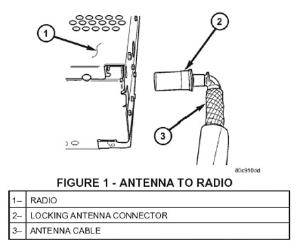
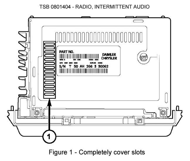
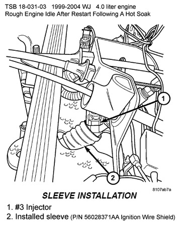
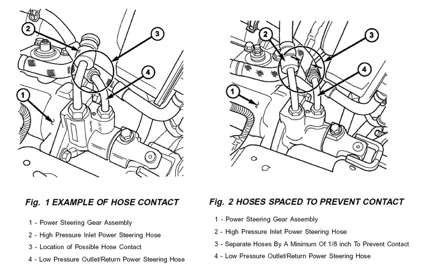
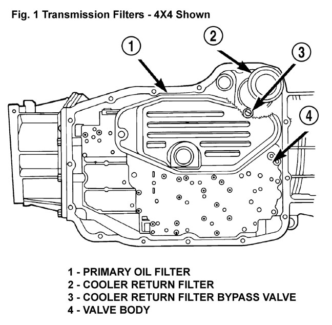
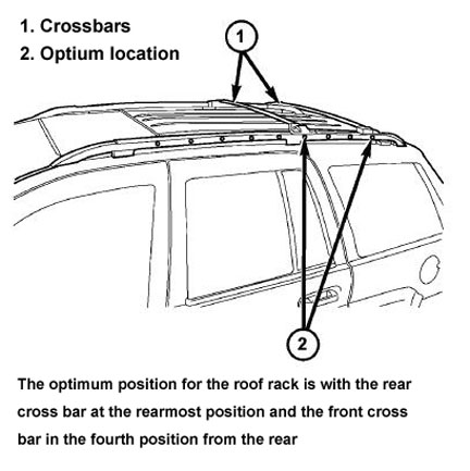
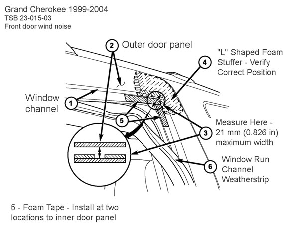
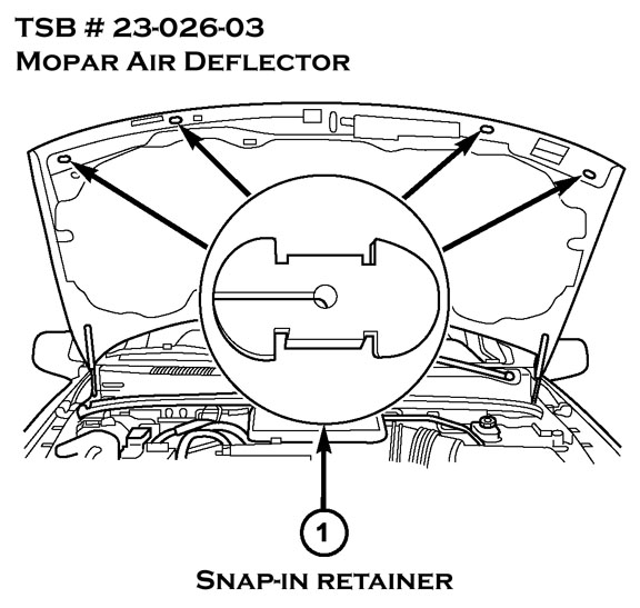
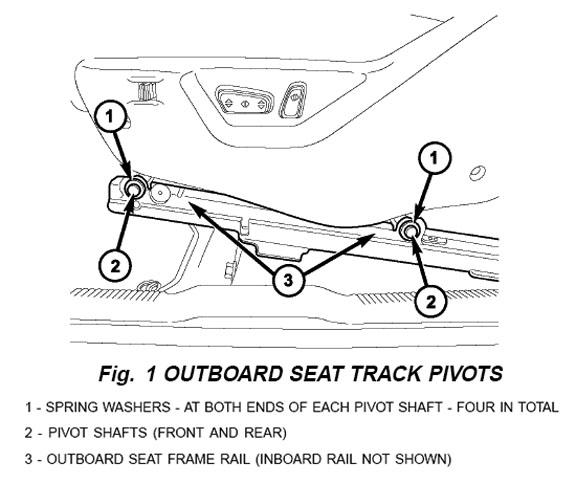
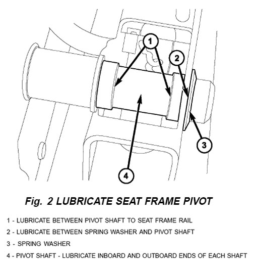
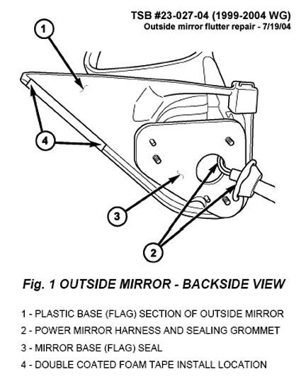
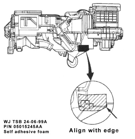