 |
|
 |
| When adding a factory CD changer to a 1999-2004 Grand Cherokee that came equipped without one, a cable must be run from the radio back to the right side cargo area where the CD changer unit is installed. The installation of a factory CD changer in these vehicles requires a compatible radio (equipped with a "Mode" or "CD-C" button). For the RB1 navigation radio with a Sirius receiver installed, an optional "Song-Artist display" cable is available which is also routed from the radio to the rear cargo area. This page describes the procedure for routing either one of these cables. |
|
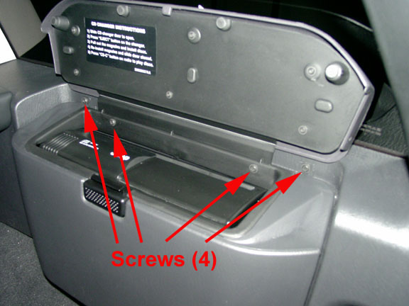
1. Remove CD changer (if equipped):
B. Lift compartment housing straight up an inch or so until it stops and then pull straight towards you to remove.
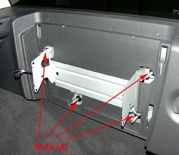
C. Disconnect the wire harness connector on the left side of the changer unit.
D. Remove the four metal bracket nuts with a 10mm deep socket (photo above right). The changer unit with its bracket attached can now be removed.
Or:
1. Remove rear storage bin (if equipped):
A. Open the storage bin lid and remove screws on each side of the lid hinge.
B. Pull upward sharply on the bottom of the bin to disengage hooks.
C. Raise bin and move inboard to disengage the quarter trim panel.
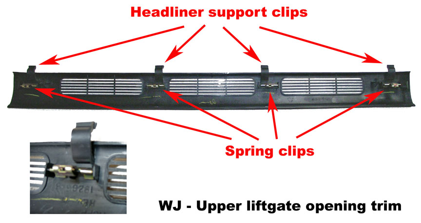
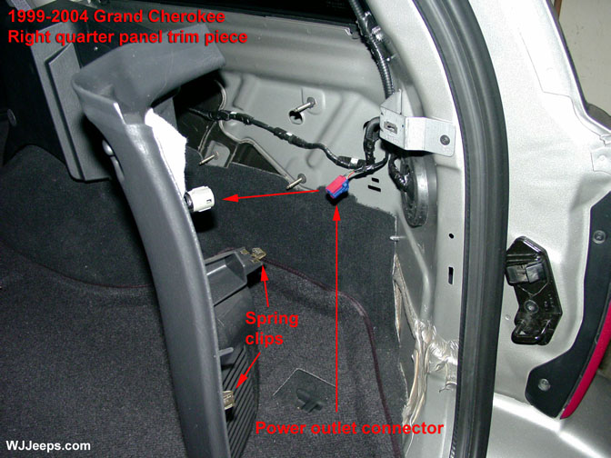
A. The trim piece is held in place with four spring clips. Grab the edge closest to the front of the vehicle with your fingers and carefully pull it down enough to release the spring clips, working from one side of the vehicle to the other. B. Tilt the trim piece down from the edge that is closest to back of vehicle and slide it towards you to disengage the four headliner support tabs. NOTE: When reinstalling the trim, note the pointed plastic alignment tabs and make sure that they and the spring clips are properly aligned before pressing the trim back into place.
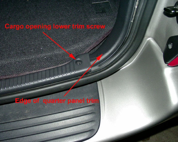
C. Remove the phillips screw on the right side of the lower liftgate opening trim piece. This will allow the quarter panel end tab to be pulled out from under the lower liftgate trim piece when it is removed.
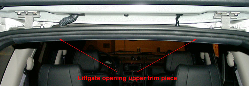
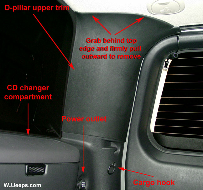
A. Grasp trim at the top and pull it towards you. It is held in place by two strong spring clips and two round plastic alignment posts. See photo above.
A. The hooks are attached to the quarter panel trim with long phillips screws.
Fold down the right rear seat. Pull the trim outward from the back (see photo above). The trim is held on with spring clips, two in the back and two more in the front. Work your way to the front, pulling outward, to completely remove the trim. Note: When reinstalling, make sure that all of the plastic guide pins and metal spring clips are aligned properly to their slots before pressing the trim pieces back in to place.
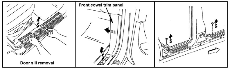
Remove the sill scuff plates by pulling them upwards. The plates are held in place with molded in snap retainers. See photo below.
Remove screws attaching cowl trim to floor. Remove the plastic nut on the front side of the trim. Grasp trim and pull outward to separate from clip. See center photo above.
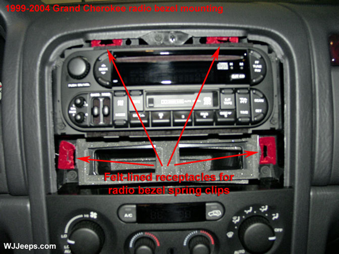
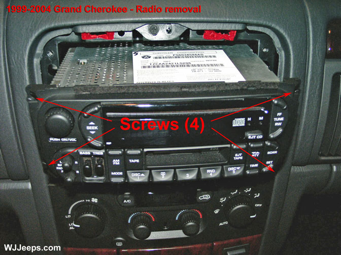
A. The radio/vent trim bezel is held in place with 4 spring clips. With a wide flat tool (a 3" plastic spackle tool works great), gently pry on each vertical side and carefully pull the bezel out a little at a time until it is free. The red areas in the center picture are the felt-lined receptacles that the bezel spring clips fit in to, which shows the general area of where to pry when removing the bezel. B. The radio is secured with four phillips screws, one in each corner. C. Slide the radio straight out and remove the wiring harnesse(s), antenna connector, and CD changer connector (if equipped). 1999-2001 models may have an additional single wire connector for the PCI connection and also a ground wire connection. Note that on the new 2002 and up models the antenna is locked onto its connector on the back of the radio. The outside collar of the antenna connector must be slid back in order to release the cable.
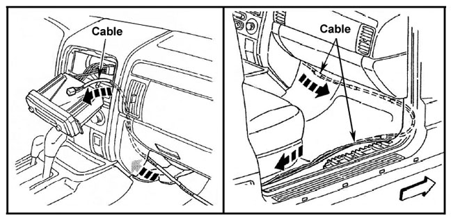
A. Run the cable starting from the rear cargo area. At this time just lay the cable roughly along the path all the way to the radio, before securing it. From the dash/radio area start securing the cable along the way to the back. Tuck under the carpet where possible. Leave a minimum amount of slack when running the cable as it is just the right length.
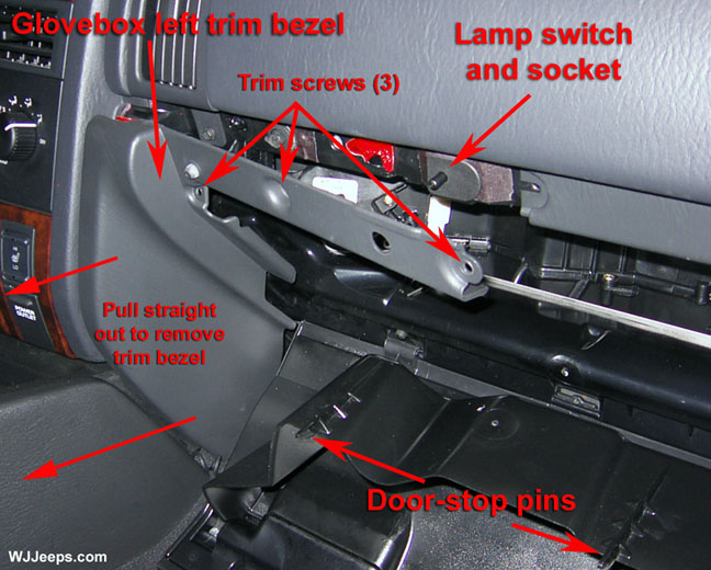
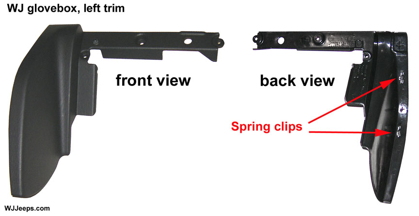
The glove box left trim piece must be removed to route the cable to the radio. Remove the 3 trim screws as shown in the photo above left. Grasp the bezel at the bottom, around the back edge, and firmly pull it straight out. In addition to the screws the bezel is secured with 2 spring clips, as shown in the right photo. Behind the trim is an opening to feed the cable over to the back of the radio.
A. Once you have finished routing the cable, hook up the cable to the radio and to the CD changer or satellite radio junction box. Test the operation of the components before reinstalling the trim pieces. When reinstalling the trim pieces, be very careful to align any alignment tabs and/or spring clips before pressing the trim pieces on securely.
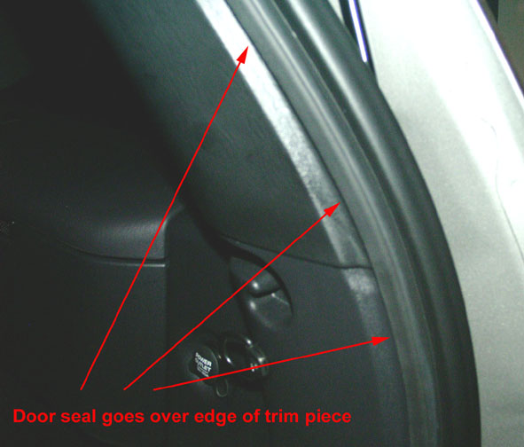
For the quarter panel trim and the upper D pillar trim piece, confirm that the door opening rubber molding is positioned over the trim pieces along the entire edge, and also along the top edge of the cargo door opening, as shown in the photo above. |